- Joined
- Jan 14, 2011
- Messages
- 75,910
- Location
- Gillette, Wyo.
- Tagline
- Halfbiass...Electron Herder and Backass Woof
Yeppers!

I like those Pomona clips. they come in every color of the resistor color code rainbow from Mouser.Here ya go...

VR1:
C pin: 20.2 (the relays engaged for 2 power ups just now, previously this voltage was 7.6)
C pin 2nd test: relays did not engage, you get 7.6 volts when this happens, meters peg 30 seconds after power down then go down slowly
A pin: 0v
R pin: 2.5v
VR2:
C pin: 0v
A pin: -20.5
R pin: -17.9
Hello Darcy, seems you have an intermittency going on of some form. The regulator VR1 is the misbehaving circuit. As a first step, I would be inclined to lift one end of the 30V zener diode D80 as a test to see if this has any bearing on the results.
Make sure that things are fully powered down and fully discharged before any solder operations are attempted.
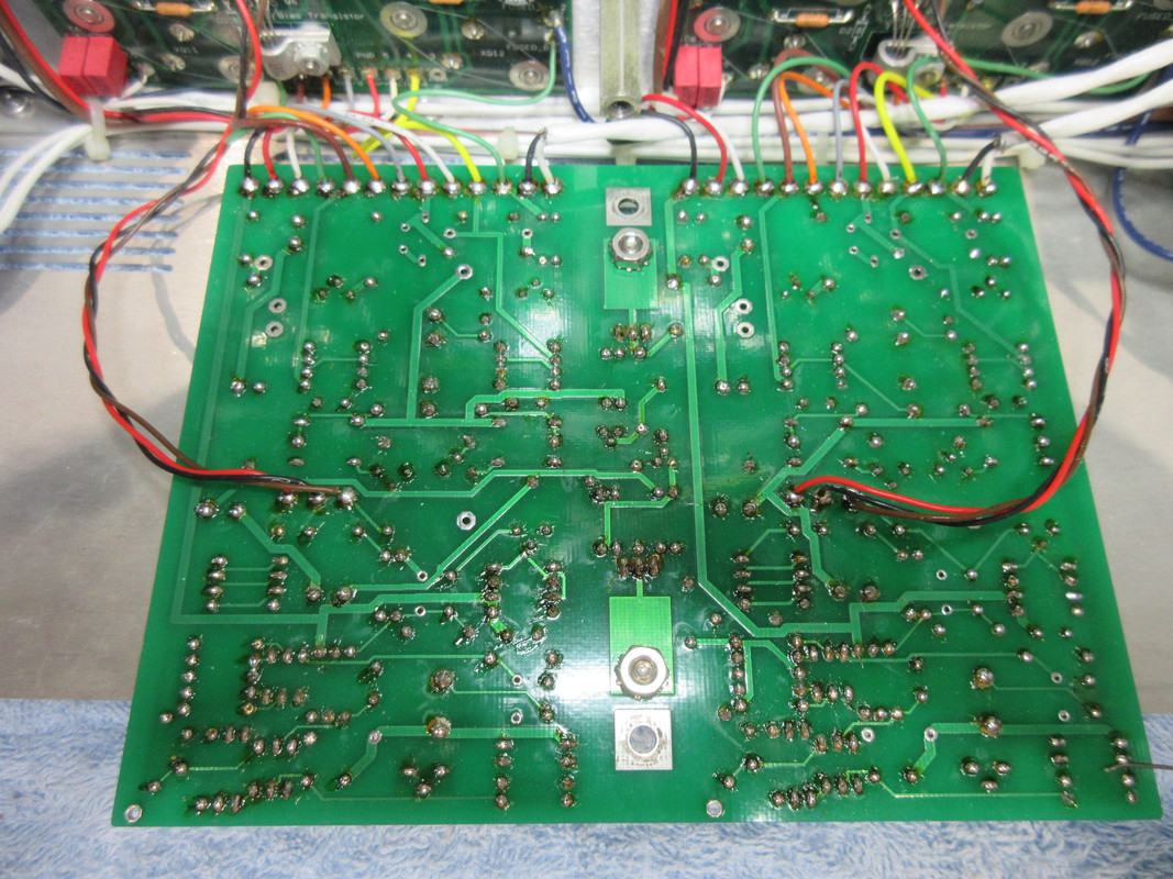
Also look around for cold solder joint, broken solder joint etc. around R85 (20.5K ohm 1/2W) and Q1 (MJE15032)Thank you Joe. I will look into this tonight and reply.
Also look around for cold solder joint, broken solder joint etc. around R85 (20.5K ohm 1/2W) and Q1 (MJE15032)
The fact that this regulator sometimes comes up properly with proper voltages makes an intermittent seem quite possible.
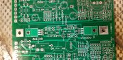
Here ya go Darc, this will help you identify the components ..
Why are pin three's of the Backplane Boards not connected to Pin three's of the Control Board?
Why are pin three's of the Backplane Boards not connected to Pin three's of the Control Board?