Michael F
Journeyman
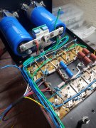
I like the bridge PCB, is that something new on the market?I think this is as far as I'm going tonight...

I like the bridge PCB, is that something new on the market?I think this is as far as I'm going tonight...
That little board is such a touch of class.I like the bridge PCB, is that something new on the market?
I am awaiting delivery on a reorder of the base board, days away from having them back in stock. They sold out faster than I expected.Joe designed these and, last time I looked, he has those in stock - a nice touch for the rectifier circuit.
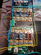
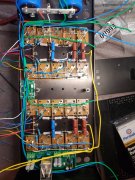
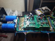
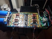
Gary do you really have the bridge rectifier mounted where it is in the picture? Not on the transformer?little more done for today from different positions. I hope to mount the transformer this weekend and apply power to the back wall and take measurements for all to see. Sure, a lot easier to work on without the transformer mounted. How's it look so far?
Why do I feel I'm in trouble?Gary do you really have the bridge rectifier mounted where it is in the picture? Not on the transformer?
See rectifier as mounted on back of the "plate" busbar in old 700 that has no cradle.

I think I can make that work. I'll look into it this evening...
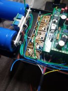
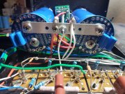
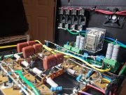
I recommend you make every effort to mount the rectifier on the left chassis wall between the capacitors for the following reasons:Gibsonian, Thanks for the subjection on bridge relocation.
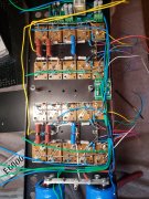
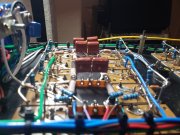
Joe is this better? You have any other ideas?
If this looks good to all, I'm going to continual only after I hear something back - good or bad.?
Agree fully. Gary wasn't it located there originally?I recommend you make every effort to mount the rectifier on the left chassis wall between the capacitors for the following reasons:
- Greater heat sink for the rectifier
- Keeping AC noise away from the main system star ground (buss bar).
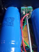
Joe, Yes, they were located on the side wall. The old capacitors were glued to the wall and were 1.75" diameter. Carvers old bridge was 25 amp and small.Agree fully. Gary wasn't it located there originally?


Everything fits because your using Joe's set of capacitors. His set measures 1.75 in diameter and mine are 2.0 in diameter. Let me put a capacitor kit on order with Joe. Thats why I relocated to another spot the bridge. Everyone, thanks you for the guidance!!Here is what I did with bridge rectifier View attachment 80320View attachment 80321View attachment 80319