gary33030
Journeyman
- Joined
- Aug 28, 2022
- Messages
- 88
- Location
- Homestead, Florida 33035
- Tagline
- I've had Phase Linear before!

I have to take that as a complement. This is board #3 for me. Thank you!Nice work on that Control Board. Your soldering skills are commendable.
In a word, yesIs a Film Capacitor and a Metallized Polypropylene Film Capacitor interchangeable?
OfCourse all the spec matches.
Thank you..In a word, yes
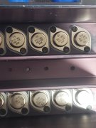
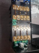
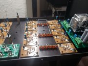
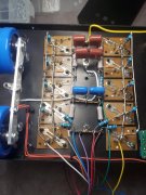
HelloLeft back plane of my Carver C-500 almost done. Thats all for tonight.
You sir are 100% correct. I did rail to output not rail to ground. I will correct this, this evening before I do anything else. Thank you. When you say to add 2 1.5UF metal capacitor, do you mean from rail to ground also? Both capacitors wired in parallel?Hello
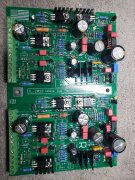
interesting layout. Your Mylar .33uf cap need to go from rail to ground . In the photos it appears to me they go from rail to output, but I may not see it correctly. Also you would be happy to add a 1.5uf metal film caps along wi these .33uf caps. I use 2 1.5 on each rail along with a .33 or .15 cap in this size amp.
Yes in parallel and space them apartYou sir are 100% correct. I did rail to output not rail to ground. I will correct this, this evening before I do anything else. Thank you. When you say to add 2 1.5UF metal capacitor, do you mean from rail to ground also? Both capacitors wired in parallel?
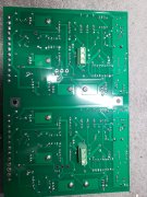
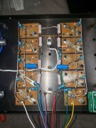
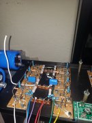
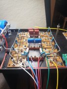
Does this look any better? (250v 1.5uf 5% film capacitors) It definitely much easier working with Joe's Back plane boards.Yes in parallel and space them apart
Don,What's the purpose of all of the paralleled film caps? It is preferable that the common connection of the film caps be isolated from the chassis ground and connect directly to the ground bus bar. Likely won't make a difference, but that is best practice.
Thank you for the explanation. Hopefully Don will see the response....the film caps Make a difference.
They are there to deal with any inductance in the rail supply wires. The closer to the collector of the outputs the better they work. Spread evenly between the four outputs is best.