gene french
Veteran and General Yakker
- Joined
- Mar 6, 2022
- Messages
- 5,888
- Tagline
- music...the healer of souls...
last 3 rather...the first one did not...

If you think a output may have a bent pin or they were just very hard to line up, then check them against one of the original sockets. The pins were very blunt on the last amp I built compared to the two prior amps. Several outputs needed a little tweek, then no issues.
Also as Joe says, photos. Joe spots issues right away.
Thanks everyone I will update you tomorrow. Have a good night.
Good morning. I just wanted to ask if the testing in the bringup instructions is required or if I could just redo the power transistors and check each row with the DBT? Because I don't have the resistors required lying around.
Rushing is a recipe for disaster PeterThanks Joe for the help, and for having patience with this newbie. You're spot on George-I'm rushing.
Any Chupacabra round there Gene?View attachment 67832
nutria rat...as they are referred to here....and yes, they are quite tasty....
good morning phoenix....
how is the build coming along????
no....north as far as panamaAny Chupacabra round there Gene?
Any Chupacabra round there Gene?
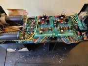
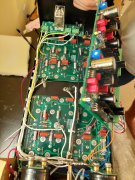
The green wire from the copper input jack plate to the bus bar ground between the 2 bulk caps is not required or desired, should be removed. You should be able to temporarily disconnect the shield connections to PAD 2L and 2R and confirm that there is NO CONNECTION of this copper plate to the chassis or to the bulk cap bus bar ground. After confirming that, reattach the shield connections to PAD 2L and 2RSorry for the large photos. I misplaced my other phone. Will try to take more.
The glow is mainly from the output bias setting, as you turn the bias down, you will notice the DBT get dimmer.With my Variac at 120 VAC output, and a 75 watt bulb in the DBT, my bulb showed a deep orange glow, but no where near white light spectrum. Are you seeing white light?