My thinking is Shorting C and E. Should create an equal output from both pre drivers and show none or very little Bias voltage
shorting C to E should result in zero bias and it turns the amp into a class B amplifier.

My thinking is Shorting C and E. Should create an equal output from both pre drivers and show none or very little Bias voltage
Rightshorting C to E should result in zero bias and it turns the amp into a class B amplifier.
Right
the problem at the moment is the high base voltage equal to the positive rail
Thanks JoeThat is a symptom, not the cause. You need to find the cause. What is the op amp doing? Is its output sitting at the +15 extreme? Is the class A NPN transistor any good or is it roached?
Please explain what this latch up isDid it latch up Maybe?? With new caps sometimes the 14 board would do that.....
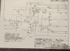
The only cap I did not replace while trouble shooting was the 47uf 100 volt which is part of that bias circuit
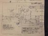
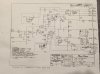
Here is the circuit for full comp
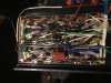
It is the original Zoebel network. Two 10 ohm carbon resistors and a .1 cap 500 volt Sprague. Both checked out ok so reused them.Whatcha got for a Zoebel network??
Will doHi Glen
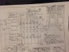
The resolution on your markup photos is pretty low. Any way you can put up one that can be read when you zoom in?
Will do
Hi Glen
The resolution on your markup photos is pretty low. Any way you can put up one that can be read when you zoom in?
It looks like you added miller caps to the 2N5416 and 2N3439. Not sure where that came from? What value did you put there? I also see a note about jumpering the 22 ohm resistor in the collector leg of each of those as well. Is the a reason why?
Joe the Miller caps are not present as of now. I plan on using 47pf silver mica caps. This was added per the service bulletin pictured.
The resistor is removed and jumper added. This is in the path shown in the full comp segmatic pictured. The other components are also removed as crossed out in my segmatic not on the phase linear segmatic attached. I have a photo of full comp board attached and I do not see this resistor.
You will note the correction in the reversing the E and C on the 2n5416 on my segmatic. This is incorrect on the phase linear comp one. This is also shown in the 2nd attached service bulletin.
More photo's
Hi had problem getting high res photo loadedI have all those Glen, I was looking for a high res photo of the schematic you marked up in the earlier post #182