
You are using an out of date browser. It may not display this or other websites correctly.
You should upgrade or use an alternative browser.
You should upgrade or use an alternative browser.
The ultimate dual 500 "rising from the ashes" build
- Thread starter grapplesaw
- Start date
- Joined
- Jan 14, 2011
- Messages
- 75,905
- Location
- Gillette, Wyo.
- Tagline
- Halfbiass...Electron Herder and Backass Woof
Those look familiar........
- Joined
- Jan 14, 2011
- Messages
- 75,905
- Location
- Gillette, Wyo.
- Tagline
- Halfbiass...Electron Herder and Backass Woof
Need some clips to hold the fan in place
one more fab job for the weekend. Now if only I had a machine shop Lee
View attachment 23813View attachment 23814
(Not actual unit only used for illustration )
The horizontal configuration of the heatsink fins certainly doesn't help the natural convection part of the equation does it?? Damn, that was a mouthful for first thing in the morning!
grapplesaw
Veteran and General Yakker
Ed you are on to something. It looks like 1982 this was added.
The came from a touring PA company that Perry got them from. This circuit is able to Handel feed back so maybe was on some horns or something that was hard to control. The high frequency circuit here has no real use in a home system. The next one I do will have a different control board.
View attachment 23659
Mystery solved!!!
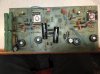
these two were in the 15 volt B+ and B- supply to the op amps. One was run to a strange point but it was functional. I have added new caps run a little more direct but with only 33uf 50 volt. I can up then later if needed. I also added two .01uf into the same circuit.
So so board ready to go back in with 100pf slow down caps on the output transistors. This is now configured full complimentary output. I put in op amp sockets so I can upgrade later. For now I will use the stock lf351. Heavy duty step down resistors rescued from an other build.


Last edited:
- Joined
- Jan 14, 2011
- Messages
- 75,905
- Location
- Gillette, Wyo.
- Tagline
- Halfbiass...Electron Herder and Backass Woof
Son when do you fire this puppy up???
grapplesaw
Veteran and General Yakker
I have been working 14 hours a day this last month. Not much time to work on it. I hope to get some juice through it tomorrow if the honey do list is manageableSon when do you fire this puppy up???
- Joined
- Jan 14, 2011
- Messages
- 75,905
- Location
- Gillette, Wyo.
- Tagline
- Halfbiass...Electron Herder and Backass Woof
I hear that Glen, ditto here...
grapplesaw
Veteran and General Yakker
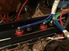
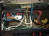
A little head way tonight. #12 supply and outs. # 20 board connects #16 board supply and ground. #12 ground to backplanes
Attachments
Last edited:
grapplesaw
Veteran and General Yakker
- Joined
- Jan 14, 2011
- Messages
- 75,905
- Location
- Gillette, Wyo.
- Tagline
- Halfbiass...Electron Herder and Backass Woof
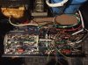
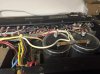
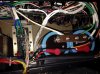
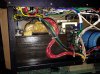
A rather intimidating point to point wiring job Glen, and it looks good....
grapplesaw
Veteran and General Yakker
A rather intimidating point to point wiring job Glen, and it looks good....
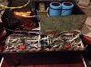
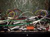
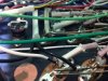
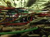
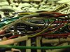
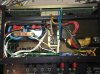
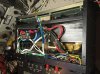
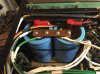
Yes it it is quite a lot of sorting out. Remember this is not a rewire job. It is a rebirth of a sort. The lessons learned here have been attempted on this project to build a full complimentary unit. It should act and work as good as any 700. With a little more punch ( not a whole lot more as it should put out 64 volts in 8 ohms)
so it has new backplanes, updatedand reconfigured control board and a complete new wiring
design.
Attavhed are some more spaghetti shots
Attachments
Last edited:
- Joined
- Jan 14, 2011
- Messages
- 75,905
- Location
- Gillette, Wyo.
- Tagline
- Halfbiass...Electron Herder and Backass Woof
I think you need big props for just finishing that project...
grapplesaw
Veteran and General Yakker
Thanks LeeI think you need big props for just finishing that project...
grapplesaw
Veteran and General Yakker
The big problem is the top and bottom plates are dented. I have seen working on saving those today. May need to get some new ones made. We will see.
- Joined
- Jan 14, 2011
- Messages
- 75,905
- Location
- Gillette, Wyo.
- Tagline
- Halfbiass...Electron Herder and Backass Woof
The chassis covers?
grapplesaw
Veteran and General Yakker
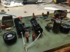
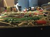
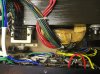
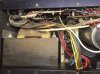
Here are shots of it right side up
just output to connect to DCP relay and tighten up a few things. First row will go in tomorrow and we will how the DBT goes.
Please check mr. Murphy at the door.
just output to connect to DCP relay and tighten up a few things. First row will go in tomorrow and we will how the DBT goes.
Please check mr. Murphy at the door.
Attachments
grapplesaw
Veteran and General Yakker
That is rightThe chassis covers?
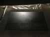
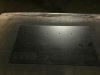
have to do some heat and shrink. There are many dents which have stretched the plate and worked the plate a bit.
I sanded them down and will see if my auto shop skills are still with me.
Attachments
Last edited:
- Joined
- Jan 14, 2011
- Messages
- 75,905
- Location
- Gillette, Wyo.
- Tagline
- Halfbiass...Electron Herder and Backass Woof
Amen brother Glen...
grapplesaw
Veteran and General Yakker
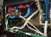
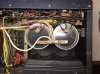
Wiring now finished. Need to add fuses and work on bypassing the power relay. Will set up the dim bulb and power up slowly.
Here are are some comparison shots
Here are are some comparison shots
Attachments
Last edited:
grapplesaw
Veteran and General Yakker
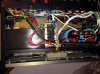
put some juice to it today.
Ugh!!
just put 12 volts across the caps and got 1 volt DC out of each output with and without fuses installed. As well got same voltage on Right bias measurement.
Starting to look for a source. That looks like getting the 15 volt op amp supply coming through some were. i checked the wiring design and will have to check the diodes etc,