- Joined
- Jan 14, 2011
- Messages
- 75,918
- Location
- Gillette, Wyo.
- Tagline
- Halfbiass...Electron Herder and Backass Woof
Not yet, still reading..

Post 152 on pg 16 may have been some of your trouble. When you were having problems getting the power supply wired you could have caused this damage.
You powered up with the power supply wired wrong once in there. You got it squared away but never got this far since then. Replace the pico fuses and the 1 ohms and I think you'll be OK. Order some TL 431 voltage regulators too, just in case the -15 volt regulator is fucked...
I think Dennis' life is a little nuts now. So I don't mind waiting a bit longer. He's come through a bunch of other times. It'll work out.
This is exactly why I will never attempt one of these builds, I just don't have the patience. The amp would be flying across the yard by now
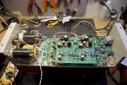
My on again, off again project has hit yet another snag. I replaced the TL 431s on the board, plus all four of the pico fuses before, once again, attempting to breathe life into my WOPL 400. All went well, until it didn't. I went through the Variac and DBT process with no apparent problems. The DBT came on with full brightness, then dimmed down somewhat. I thought it was a little bright for idle, but when I looked on my meter, the unit was pulling no more than half an amp – 0.453. So I thought everything was okay. Then I plugged it directly into the AC — no noises, no smoke, no nothing for about 15 seconds. Then, just as I was turning away to get the DMM and start checking voltages, there was a pop and a puff of smoke. A resistor in the left channel blew, and I shut everything down immediately. It's R24L, 182 Ohm. I feel like an idiot, repeatedly having problems with this amp. But it's actually rewarding. With every problem, I learn something new. So I'm still plugging away, even though I need to again ask for some assistance from you much more experienced guys. Does anyone have any thoughts about this particular resistor blowing up?
Hi Scott
When you look at this resistor in the schematic, you will see that this 182 ohm resistor is shunted by one of the 0.33 ohm emitter resistors on the backplane board. If this resistor is not blown open on the backplane board then you should not be able to experience damage to this resistor. It feeds the base of the upper half protection transistor. A key to this is why your nearly 0.5A line current is occurring. That is nearly 60W sitting at idle which should not be the case.
When you were on the DBT, what was the bias on this left channel reading at and what was the output offset voltage? You should be able to put it back on the DBT and get that ascertained. The resistor you smoked is not critical to the proper operation of the amp, just the protection circuit.
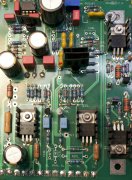
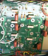
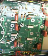
Double check that you do not have an open solder joint on backplane resistor R35. Cannot see any of that in your photos. It would also help to get us some higher rez photos. These are somewhat grainy which makes it hard to blow up and see anything.
identical to the PL700 PerryJoe, does the 400 BP boards mount like the 700's? His ground lug set up could be causing board flex/short the way it is.