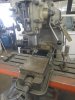
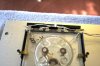
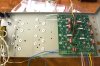
Did you check the transformer for proper operation before assembly? Looks good so far!
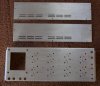
Did you re-do the silk screen on the faceplate? I was thinking about adding a white oak WOPL or what ever to the 400 I just completed but have no experience with having silkscreen done. The idea will be to have it match the plastic insert on the 700b that is it's companion amp that will be built soon.
From the other thread in reference to the output devices, you can get those from Joe or Mouser.
Post lots of pics, the more experience builders will be able to pick out errors in the pictures rather than you finding them at start up... or just provide suggestions.
In my own experience I would encourage you to read a couple build threads and all the info given by Joe via email before starting.
Actually, I'm getting some parts from Nav, who seems more than prepared and stocked with what I need. Also, you can get silkscreening done by companies that do such things, you just need to Google around your area. However, I'm not interested in the old silkscreening. I've actually begun painting my two faceplates (I have this 400 and a rebuilt Series II I bought new in 1980).

I'm shooting them with black acrylic lacquer. I'll eventually sand the painted plates with 1500 grit sandpaper and rub the surface out so that it's like glass. Also, my friend pin-stripes and letters Hot Rods and I'm having him logo my faceplates. I grew up next door to the Black Hawk, a very famous, old (long gone) Jazz club here in San Francisco. Google it. A lot of great Jazz albums were recorded live there — including an amazing Miles Davis record. We used to climb up on the roof and sneak through a broken door (we broke it), and watch the shows from a crawl space you could access from there. We laid on our bellies and watched from just above the stage. We saw
everybody there. That club was a big part of my musical education, in fact, a big part of my life back then.
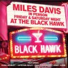
So, just for fun, the logo I've made up is the Black Hawk graphics seen on this record, minus the marquee. Goofy, I know, but it means a lot to me, so my buddy's going to paint that logo directly on the faceplates. I thought about anodizing the aluminum, but decided on the Hot Rod look instead. Engraving is also very affordable. You could reproduce the original screenprinting with engraving, then use paint to color the letters and lines. It's easy to do. You can also easily make your own 700 plastic insert and have that engraved as well.
And, no, I didn't check the transformer, so I guess we'll see. How do you check a transformer. I could still easily hook up some jumpers.