If you had the red collector lead open, your bias would be off the charts causing yuuuge topside into bottom side current. I suspect you took out an emitter resistor, or two or three.

You are using an out of date browser. It may not display this or other websites correctly.
You should upgrade or use an alternative browser.
You should upgrade or use an alternative browser.
Resurrected a Customized WOPL 400
- Thread starter scottonnob
- Start date
WOPL Sniffer
Veteran and General Yakker
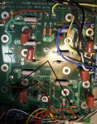
The bias transistor's are crooked, and the ground lug is missing some nylon washers
WOPL Sniffer
Veteran and General Yakker
scottonnob
Journeyman
- Joined
- Apr 28, 2015
- Messages
- 251
- Tagline
- ---
As far as I can recall, and I'm pretty confident about this, my kit did not come with such washers. There were small nylon washers, but nothing like what you are showing. And, as far as the transistors are concerned, I know they're crocked. They turned that way when I tightened them down. I didn't want to run the risk of breaking any of the leads by moving it back, so I just made absolutely certain that nothing was shorted out.
scottonnob
Journeyman
- Joined
- Apr 28, 2015
- Messages
- 251
- Tagline
- ---
Also, that is not the backplane board I have. I know that doesn't negate what you observed about the ground hardware, but I know nothing like that came my way. I certainly have such hardware here, but it didn't come from WOPL.
WOPL Sniffer
Veteran and General Yakker
without the nylon washer to sit on the standoff, the board will flex and you stand the chance of shorting it out, cracking runs and you won't get a good ground. The little threaded stand off should protrude through the board about the thickness of the nylon washer so when tightened down it won't hurt anything. a pair of them, along with the fender washers should have come with the back plane kit.
WOPL Sniffer
Veteran and General Yakker
Also, that is not the backplane board I have. I know that doesn't negate what you observed about the ground hardware, but I know nothing like that came my way. I certainly have such hardware here, but it didn't come from WOPL.
You have the 400 back planes but they mount the same.
First post here, but same issue happened to me this past Spring when building two 400 full WOPLs for a 2.2 system. I stressed those small wires by cleaning off the flux with alcohol and a tooth brush. Then stressed them more during assembly. I didn't notice strands were broken, and on power up the remaining strands let go with a flash and a pop. Hard to remember, but I think only 1 pico on the backplane was taken out. I decided then to use screw jacks after this, think they're listed at end of the BOM as optional. Kind of crazy not to use them with those big through plated holes. So, assembly is a breeze and that small diameter wiring is more robust when secured so on both ends.
Also, get new silpads, very, very lightly lube the output bolts so the threads aren't dry, run them in and out a couple times until they feel smooth, then install the outputs. Use a magnvisor
Also, get new silpads, very, very lightly lube the output bolts so the threads aren't dry, run them in and out a couple times until they feel smooth, then install the outputs. Use a magnvisor
First post here, but same issue happened to me this past Spring when building two 400 full WOPLs for a 2.2 system. I stressed those small wires by cleaning off the flux with alcohol and a tooth brush. Then stressed them more during assembly. I didn't notice strands were broken, and on power up the remaining strands let go with a flash and a pop. Hard to remember, but I think only 1 pico on the backplane was taken out. I decided then to use screw jacks after this, think they're listed at end of the BOM as optional. Kind of crazy not to use them with those big through plated holes. So, assembly is a breeze and that small diameter wiring is more robust when secured so on both ends.
Also, get new silpads, very, very lightly lube the output bolts so the threads aren't dry, run them in and out a couple times until they feel smooth, then install the outputs. Use a magnvisor or other magnification to closely watch the edge of the silpads just begin to curl or wrinkle, then stop, no tighter.
WOPL Sniffer
Veteran and General Yakker
without the nylon washer to sit on the standoff, the board will flex and you stand the chance of shorting it out, cracking runs and you won't get a good ground. The little threaded stand off should protrude through the board about the thickness of the nylon washer so when tightened down it won't hurt anything. a pair of them, along with the fender washers should have come with the back plane kit.
Correction to my post: Using the Nylon spacer, and the fender washer is how I prefer to put the back planes in. It keeps the boards from getting flexed due to over tightening BUT, If mounted with care, they DO NOT NEED TO BE used like I use them. With my 47" biceps, I tend to break grade 8 bolts, and I sit down to pee!!!
") you can never be to careful.
you can never be to careful. Follow Joe's directions and you'll win every time. Carry On!!!
scottonnob
Journeyman
- Joined
- Apr 28, 2015
- Messages
- 251
- Tagline
- ---
First post here, but same issue happened to me this past Spring when building two 400 full WOPLs for a 2.2 system. I stressed those small wires by cleaning off the flux with alcohol and a tooth brush. Then stressed them more during assembly. I didn't notice strands were broken, and on power up the remaining strands let go with a flash and a pop. Hard to remember, but I think only 1 pico on the backplane was taken out. I decided then to use screw jacks after this, think they're listed at end of the BOM as optional. Kind of crazy not to use them with those big through plated holes. So, assembly is a breeze and that small diameter wiring is more robust when secured so on both ends.
Also, get new silpads, very, very lightly lube the output bolts so the threads aren't dry, run them in and out a couple times until they feel smooth, then install the outputs. Use a magnvisor
Yeah, you and I are of the same sensibility on the lubricant. As an old race car guy, I never put fasteners together without lube. On a race car, everything is secured, unsecured, and resecured so many times that chatter is always a problem, especially on aluminum, particularly for getting accurate torque settings, especially on engine parts.
scottonnob
Journeyman
- Joined
- Apr 28, 2015
- Messages
- 251
- Tagline
- ---
Okay, going out now to try this again. Gonna reattach the red collector lead, check all the emitter resistors, and reassemble with all the proper hardware. Then I'll power back up and check everything Joe recommended. If all's well, I'll change out that resistor and see if I can't get it right finally. Thanks everyone for the assistance.
Because there was so much dialog in this thread, it prompted me to add this wording to clarify the use of the Assembly Aid hardware to the assembly instructions in the first page. Please squawk back if you do not find this clear. There is dialog about its use in the step by step but sense that the intent may be getting lost so added this, upfront.
Note regarding the Assembly Aid hardware that is supplied with your kit. This hardware kit provides items that will help you keep things together during the assembly process and will be removed when the assembly task is completed.
Note regarding the Assembly Aid hardware that is supplied with your kit. This hardware kit provides items that will help you keep things together during the assembly process and will be removed when the assembly task is completed.
- There are 2 large nylon washers and 2 fender washers that will serve to hold the backplanes temporarily in place over the round upper standoff studs while you complete other wire connections and heatsink installation. It will keep all the nylon shoulder washers securely in place in the chassis holes during those processes. The nylon washer goes around the upper 2 round spacers followed by a fender washer on top of each followed by a 6-32 hex nut.
- There are 8 small nylon washers and 8 flat metal washers also in this kit. These help to temporarily hold the heatsinks in place until you get all the output transistors installed which will do the final task of holding the heatsinks in place. Using 8 of the 6-32x1/2” socket head screws provided in the normal hardware bags, put a flat metal washer followed by the nylon washer on each screw and while holding each heatsink temporarily in place, install one of these screw and washer combinations in the uppermost transistor securing hole. Install a second one on each heatsink in the lower hole of the second transistor up from the bottom. This will leave the bottom transistor row unobstructed for installing the driver transistors to accomplish initial bring up. This hardware combination using the nylon washer keeps the mechanical connection from shorting out backplane connection to the heatsinks and therefore chassis ground. Once you get the bottom transistor row successfully installed and tested, it will allow you to remove the lower screw and washer combination and work your way up as more output transistors are installed. When you have completed all steps, these metal washers and nylon washers are no longer necessary.
scottonnob
Journeyman
- Joined
- Apr 28, 2015
- Messages
- 251
- Tagline
- ---
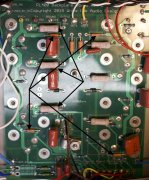
Well, it seems that there are a number of resistors on the backplane that are blown, as shown in the photographs. The layout of the board I have with my documents is different than the boards in front of me. So I’m not sure I have the numbers correct, as some can’t be seen, but I put arrows in to show what’s gone. Surprisingly, there seem to be two resistors blown on the right side as well. On the left, it looks like R5 or 6 (like I said, I don’t have an accurate, numbered layout. Even the schematic is for some other version), both 10 ohm resistors at the bottom of the board, both 150 ohm at the top, then R31, R33, and R35 – 0.33 ohm resistors on the left board, and both 150 ohm on the right side, as well — Boom! Why there’s a problem on the right side, I can’t figure out.
Attachments
mlucitt
Veteran and General Yakker
This kind of resistor demolition could be cause by what Sniff said earlier; cranking down on the temporary mounting nut/washer combination could have flexed the board enough to allow several resistors to touch the back wall of the chassis. Hard to prove unless you pull the boards and look for arcing spots (don't do it!) but it is a good theory...
No it was the runaway bias due to the missing collector wire. The bias transistor is uber critical. If that connection goes open, the bias goes from 0.35V to 150V rendering the resistors that Scott pointed out as fuses. Should have taken out at least 1 rail fuse in the process
scottonnob
Journeyman
- Joined
- Apr 28, 2015
- Messages
- 251
- Tagline
- ---
If you mean the pico fuses, they are all good. I double checked them. I checked every resistor.
mlucitt
Veteran and General Yakker
I was thinking that so many components grounded on the chassis back wall could have popped that Q6 collector wire off the board. He said he heard a pop. Sometimes resistors pop, but my experience is that they die a slow, smoky, quiet death.No it was the runaway bias due to the missing collector wire. The bias transistor is uber critical. If that connection goes open, the bias goes from 0.35V to 150V rendering the resistors that Scott pointed out as fuses. Should have taken out at least 1 rail fuse in the process
scottonnob
Journeyman
- Joined
- Apr 28, 2015
- Messages
- 251
- Tagline
- ---
So my notes say I need: 10 ohm, MF, 2W 1%; 150 ohm, MF, 1W, 1%, and 0.33 ohm, MO, 3W, 2%. Is that correct?
No I mean the rail fuses. One of the 5AGX fuses should have failed. The pico fuses are in low current pathsIf you mean the pico fuses, they are all good. I double checked them. I checked every resistor.