You are using an out of date browser. It may not display this or other websites correctly.
You should upgrade or use an alternative browser.
You should upgrade or use an alternative browser.
PL 700 Pro Build
- Thread starter George S.
- Start date
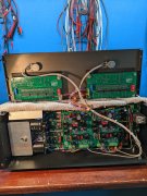
The Z2 opamp was blown, that's the one closest to the power supply.
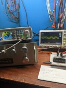
Gotta say, that scope is so easy to use, I love it! I followed a 500 Hz signal from a tuner input jack right to the dead opamp.
Really didn't even need to take the preamp apart. Live and learn.
Gotta say, that scope is so easy to use, I love it! I followed a 500 Hz signal from a tuner input jack right to the dead opamp.
Really didn't even need to take the preamp apart. Live and learn.
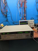
Making progress with the Panasonic AM FM Stereo signal generator. It appears to work, just needed a good scope to see it. Now to figure out how to see the difference in AM and FM modulation, and the FM pilot frequency this is supposed to generate.
Attachments
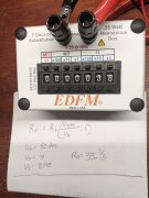
Been reading about preamp output impedance and how to measure it.
Measured it two ways. One way gives me 33 ohms impedance using the calculation.
The other way was to use a resistor decade box to exactly half the unloaded voltage seen on the scope. Unloaded the peak to peak was 4 volts. Loaded at 2 volts, the resistor decade box says 38 ohms. I am using the built in peak to peak voltage measurement function on this new scope to measure voltage.
So, a average of 35 ohms impedance on the output of my modded PL2000 S2. From what I've been reading, this seems rather low. Low appears to be good from what I've read, just surprised it's so low.
I verified the resistor box reading with both Flukes. It's accurate.
Watched two YouTube videos on doing this.
Attachments

Been reading about preamp output impedance and how to measure it.
Measured it two ways. One way gives me 33 ohms impedance using the calculation.
The other way was to use a resistor decade box to exactly half the unloaded voltage seen on the scope. Unloaded the peak to peak was 4 volts. Loaded at 2 volts, the resistor decade box says 38 ohms. I am using the built in peak to peak voltage measurement function on this new scope to measure voltage.
So, a average of 35 ohms impedance on the output of my modded PL2000 S2. From what I've been reading, this seems rather low. Low appears to be good from what I've read, just surprised it's so low.
I verified the resistor box reading with both Flukes. It's accurate.
Watched two YouTube videos on doing this.
What frequency? It may well grow higher at low frequencies.
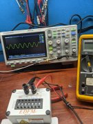
500 Hz sine wave 3 Volts peak to peak at input. Turned up the volume some to see 4 Volts peak to peak on the scope.
Left it all on the bench so I can try some other frequencies today and make sure I'm not overlooking something like I always do.
Seems like a relatively simple measurement. But I do see more complicated formulas for testing equipment that's highly reactive to the load. Going to play around with this today and see if results average.
Using the simplest measurement scheme, of halfing the the unloaded voltage with a load on the decade box. At 50 Hz the impedance is 386 ohms. At 500 Hz the impedance is 38 ohms. Interesting how the factor of 10 appears.
Time to do some more reading.
Time to do some more reading.
Attachments
Using the simplest measurement scheme, of halfing the the unloaded voltage with a load on the decade box. At 50 Hz the impedance is 386 ohms. At 500 Hz the impedance is 38 ohms. Interesting how the factor of 10 appears.
Time to do some more reading.
Not a mystery at all George, you are seeing the impedance of the output coupling cap come into play. At high frequencies, that cap approaches a short, as you go down in frequency, that cap approaches an open...
That is why I asked about what frequency you are using.
Increase the value of the output cap and your low performance will improve in a linear fashion with the increase in C.
J!m
Veteran and General Yakker
And you just know that off the top of your head...
That's awesome. (because I don't know that!)
That's awesome. (because I don't know that!)
Joe, O.K., so increase capacitance value to improve low frequency performance.
PL had two 2.2 uF electrolytics in series + to + on each output trace to create a bipolar.
Per the photograph of the old test board, a jumper replaced one cap and a 4.7 uF film the other old cap. This is how both working preamps are configured.
What should I study to figure out the optimum value for the output coupling caps. I'm at a loss for terminology and thinking I'm approaching the need of a good spectrum analyzer once again.
Attachments
J!m
Veteran and General Yakker
OH! I think I was looking at a configuration like this in an old Pioneer schematic or something.
Apparently, setting caps up this way, has some unique properties, compared to a single cap.
I have my popcorn, because I didn't understand it!
Apparently, setting caps up this way, has some unique properties, compared to a single cap.
I have my popcorn, because I didn't understand it!
Joe, O.K., so increase capacitance value to improve low frequency performance.
PL had two 2.2 uF electrolytics in series + to + on each output trace to create a bipolar.
Per the photograph of the old test board, a jumper replaced one cap and a 4.7 uF film the other old cap. This is how both working preamps are configured.
What should I study to figure out the optimum value for the output coupling caps. I'm at a loss for terminology and thinking I'm approaching the need of a good spectrum analyzer once again.
Hi George
The good news is that the move to the single 4.7uF has improved the situation ~5 fold from the original (1.1uF to 4.7uF)
You have to consider what you are driving, the PL amp input load with a RevG1. You indicated the measured impedance is 386 ohms at 50Hz which makes total sense given what you measured a decade above that at 500 Hz. Lets assume 25 Hz, your measured impedance should be somewhere around 772 ohms. Lets use that number. This means that your amp output at 25 Hz will be down approximately 1.5% from and equivalent signal at 500 Hz. Not huge but something.
Compare that to the original back to back 2.2uF situation and your 25 Hz signal would have been down ~6%. You have improved the situation significantly.
J!m,
From my perspective, Gepetto has proven by his words & his actions to definitely be one of The Elders.
Cheers --
I can definitely prove that by my age
") I am sneaking up on the Curmudgeon stage...
I am sneaking up on the Curmudgeon stage...Thanks Joe. I'm going to have to reread this several times and think about it to understand. I see I need to read up on capacitors and their effect on frequency. Thank you!Hi George
The good news is that the move to the single 4.7uF has improved the situation ~5 fold from the original (1.1uF to 4.7uF)
You have to consider what you are driving, the PL amp input load with a RevG1. You indicated the measured impedance is 386 ohms at 50Hz which makes total sense given what you measured a decade above that at 500 Hz. Lets assume 25 Hz, your measured impedance should be somewhere around 772 ohms. Lets use that number. This means that your amp output at 25 Hz will be down approximately 1.5% from and equivalent signal at 500 Hz. Not huge but something.
Compare that to the original back to back 2.2uF situation and your 25 Hz signal would have been down ~6%. You have improved the situation significantly.
Thanks Joe. I'm going to have to reread this several times and think about it to understand. I see I need to read up on capacitors and their effect on frequency. Thank you!
In the coupling application, where you want great low frequency coupling as well as high frequency coupling, bigger is better. Unlike solder connections where "the bigger the blob, the better the job" is not always the correct approach.
mlucitt
Veteran and General Yakker
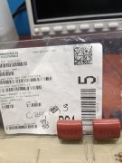
Joe, I installed the two TDK 22uF film output caps and wire jumpers in my PL2000 and the preamplifier sounds better than it ever has. I am quite sure the technology to create a 22uF film cap with 25mm lead spacing did not exist in 1979.
Mouser P/N 871-B32523R226M
Mouser P/N 871-B32523R226M
I suspect it existed Mark but PL did not want to pay the freight for film caps of that size/value.Joe, I installed the two TDK 22uF film output caps and wire jumpers in my PL2000 and the preamplifier sounds better than it ever has. I am quite sure the technology to create a 22uF film cap with 25mm lead spacing did not exist in 1979.
Mouser P/N 871-B32523R226M
J!m
Veteran and General Yakker
Panasonic and Kemet make nice film caps; the latter come quite tight on tolerance if you wish (some 1% films in the phono pre- long lead time). I ended up going with 2% ones due to the six month wait at that time. Paired them up and they are within 1%. Just get a few extras and they pair easily.
Snow day in NE Ohio, so pulled the 100k attenuators out of the 400 S2 WOPL that powers my biamp system. Installed 50k to match the 700 Pro 50k attenuators.
There's a lot about amp input impedance and it's effect on preamp output that I don't understand, but it makes sense to do this as the 700 seems to be more "sensitive" and have higher gain at the normal volumes I listen to. Need to get these balanced without going into the MiniDsp.
There's a lot about amp input impedance and it's effect on preamp output that I don't understand, but it makes sense to do this as the 700 seems to be more "sensitive" and have higher gain at the normal volumes I listen to. Need to get these balanced without going into the MiniDsp.