Very little readjustment to the Cylon meters was needed, which makes sense. What I've done is changed the input impedance that the preamp "sees". Haven't changed the ohm resistance through the coax from the RCA jack center conductor to the control board.

You are using an out of date browser. It may not display this or other websites correctly.
You should upgrade or use an alternative browser.
You should upgrade or use an alternative browser.
PL 700 Pro Build
- Thread starter George S.
- Start date
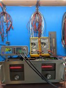
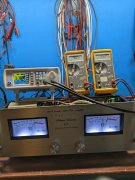
Success, makes a audible difference. Amps are now balanced. Easy to hear and see the difference on the Cylon meters. My two 400s and 700 were all built as similar as possible with Joe's WOAD parts, just needed to get the attenuators matched.
Going to do the 400 S1 WOPL after lunch.
Going to do the 400 S1 WOPL after lunch.
Attachments
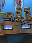
So ran into a problem with the 400 S1 WOPL and 50k attenuators. At 40 VRMS output, the meters peg. With 100k attenuators the meters were perfectly aligned at 100% at 40 VRMS output.
I don't understand why the Cylon meters were still closely calibrated but the mechanical meters aren't. Going to open her back up, find the resistor on the WOAD light board for the meter, and install a decade resistance box to find the proper value. Get those new resistors installed and retest.
I don't understand why the Cylon meters were still closely calibrated but the mechanical meters aren't. Going to open her back up, find the resistor on the WOAD light board for the meter, and install a decade resistance box to find the proper value. Get those new resistors installed and retest.
Attachments
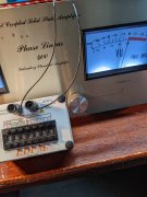
27k ohms puts the needle right at 100% at 40 VRMS output, which is 200 watts per Joe's tech documents. The WOAD light board has a 13.14k ohms resistor installed.
So, dropping the attenuator value by 50% requires doubling the resistor value to keep the mechanical meter calibrated.
Now to search for 27k resistors. Parts are not organized.
So, dropping the attenuator value by 50% requires doubling the resistor value to keep the mechanical meter calibrated.
Now to search for 27k resistors. Parts are not organized.
Attachments
Got it calibrated. 27k ohm resistors with 50k ohm attenuators. Close enough for testing. The right meter is mechanically adjusted a little too tight and I'll back it off next time I go into it. Now it's time to close it up, plug it in, and listen to some Allman Bros for testing.
Attachments
Skratch
Chief Journeyman
I use a DPDT toggle with resistors on the toggle and 0db can be 2 watts, 20 watts or 50 watts
So ran into a problem with the 400 S1 WOPL and 50k attenuators. At 40 VRMS output, the meters peg. With 100k attenuators the meters were perfectly aligned at 100% at 40 VRMS output.
I don't understand why the Cylon meters were still closely calibrated but the mechanical meters aren't. Going to open her back up, find the resistor on the WOAD light board for the meter, and install a decade resistance box to find the proper value. Get those new resistors installed and retest.
Easy answer, the original light board calibration was for 100W at the 0dB setting on the meter. The new light board (LBC) provides 3 jumperable or switchable settings for the 0dB mark, 20W, 100W (to match the stock setting) or 200W. Ask Dave (Phase Linear Phanatic), he has several of the switchable light boards that he has installed with switches on the back to match his mood.
PS: the input pot value has nothing to do with this meter sensitivity setting.
Got it calibrated. 27k ohm resistors with 50k ohm attenuators. Close enough for testing. The right meter is mechanically adjusted a little too tight and I'll back it off next time I go into it. Now it's time to close it up, plug it in, and listen to some Allman Bros for testing.
You may now be disappointed that the analog needles do not move off of zero at most normal listening levels. All of my customer requests have been how do I make my PL400 needles move more at the levels I listen at? That led to the birth of the LBC light board.
The LED meter has a log amp in it to give you some sizzle at low listening levels while flattening out at higher volume levels. Analog meters don't do that.
Vynuladikt
Journeyman
- Joined
- May 4, 2016
- Messages
- 468
- Location
- Northeast Iowa
- Tagline
- Love great audio, beermaking and pyrotechnics
Yep, my 400 WOPL barely moves the meters at "normal" listening levels. That would be for the average non PL owner. When it gets to bouncing to -10dB its about 85 to 87 dB at 12-14 ft. , my normal listening position. By the time it is nearing 0 db on the meter we're well into 100+You may now be disappointed that the analog needles do not move off of zero at most normal listening levels. All of my customer requests have been how do I make my PL400 needles move more at the levels I listen at? That led to the birth of the LBC light board.
The LED meter has a log amp in it to give you some sizzle at low listening levels while flattening out at higher volume levels. Analog meters don't do that.

Thanks guys. I really don't care if my meters don't move at normal listening levels. I never look at the amps when they're on as I'm always doing something else when listening to music. And yes, I thought the 400 S1 meters were calibrated at 200 watts, not 100, my mistake.
What's important to me is that the 400s show 200 watts on the meters at 40 VRMS and the 700 shows 350 watts at 53 VRMS.
The PL2000 S2 preamps seem to like the lower value attenuators. Seems like the amps put out more volume at a lower volume setting on the preamp. I wanted to quantify the change with some measurements but was unable to find any information for doing so.
J!m
Veteran and General Yakker
Somewhat related-
The meters on my receiver don’t move much either. That are calibrated in watts output. It gets quite loud at 1 watt with most material due to the small room. I assume the Polk speakers are reasonably sensitive as well.
The meters on my receiver don’t move much either. That are calibrated in watts output. It gets quite loud at 1 watt with most material due to the small room. I assume the Polk speakers are reasonably sensitive as well.
That is just what PL did, and told you so in the service manual. In practice that left another 3dB of power for headroom without going over the rated power. It was likely a compromise on having the needles move with reasonable power output. Like the question I receive often. “How do I get my meters to move more?”Hmmm, is there a good reason to have the 400 S1 WOPL meters show 100 watts at 0db rather than 200? I tend to overlook the obvious quite often. Just seems that calibration of 200 watts at 0 db is the way to go.
J!m
Veteran and General Yakker
Put a big ol’ load resistor on the outputs with the speakers?
There was something similar marketed to guitarists to allow them to “crank it” without deafening the town. Get into the “sweet spot” at reasonable volume.
There was something similar marketed to guitarists to allow them to “crank it” without deafening the town. Get into the “sweet spot” at reasonable volume.
I always thought the meters should be accurate like a speedometer on a car.
I do like the meter attenuation switch on the 700 that supposedly matches the 700s meters to a 400s full scale meters. But, you know, I might be wrong about this. I don't know.
Any how, I'll probably put the original resistors back into the 400 S1 so they accurately read 100 watts at the 0 db 100 marking on the meter faces. That's how they designed it, much smarter people than me.
Glen was right on the money, 1/2" longer standoffs are perfect. Finally got around to doing this.Yes indeed. Raise it 1/2” if you can.
Attachments
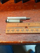
Hi GeorgeGlen was right on the money, 1/2" longer standoffs are perfect. Finally got around to doing this.
While you are in there, you might as well check this out...
First:
It is ESSENTIAL that you have the copper plate installed and connecting the 2 RCA input jacks. This shunts any external ground loops associated with cable connections from entering the amp’s separate signal paths and creating various degrees of ground looping. In other words, it makes the amp INTERNALLY immune to cabling effects from outside the amp. This does not say that you cannot still have external ground looping, it does say that this keeps the amp internals out of the equation. No build I have ever done has removed this copper plate. Remember, the RCA jacks and this copper plate MUST be isolated from the chassis.
Second:
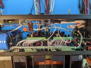
Disconnect and remove the two ground wires running from the backplane pin 5L and 5R which run to the control board pin 5L and 5R Phoenix connector.
Along the bottom, run two new, separate 22AWG wires from a single solder lug on the single point ground copper bus bar to pin 5L and 5R on the control board. The solder lug goes underneath the 10-32 (or M5 if you have our newer caps) screw on the bottom B- bulk cap positive terminal which attaches to the copper bus bar. The wire to 5L is approximately 5” long and the wire to 5R is approximately 10” long, your measurements may be adjusted to suit how you lace these in. You should be able to use one of the #10 solder lugs provided in the White Oak Audio wire kits to accomplish this.
Dress and button up the amp reinstalling all covers.
Joe, I understand and will do. Easy enough as I have Phoenix Contacts Connectors on all 3 amps and still have the copper RCA plates, plenty of wire, unfortunately mostly 16 AWG, it'll have to do.Hi George
While you are in there, you might as well check this out...
First:
It is ESSENTIAL that you have the copper plate installed and connecting the 2 RCA input jacks. This shunts any external ground loops associated with cable connections from entering the amp’s separate signal paths and creating various degrees of ground looping. In other words, it makes the amp INTERNALLY immune to cabling effects from outside the amp. This does not say that you cannot still have external ground looping, it does say that this keeps the amp internals out of the equation. No build I have ever done has removed this copper plate. Remember, the RCA jacks and this copper plate MUST be isolated from the chassis.
Second:
Disconnect and remove the two ground wires running from the backplane pin 5L and 5R which run to the control board pin 5L and 5R Phoenix connector.
Along the bottom, run two new, separate 22AWG wires from a single solder lug on the single point ground copper bus bar to pin 5L and 5R on the control board. The solder lug goes underneath the 10-32 (or M5 if you have our newer caps) screw on the bottom B- bulk cap positive terminal which attaches to the copper bus bar. The wire to 5L is approximately 5” long and the wire to 5R is approximately 10” long, your measurements may be adjusted to suit how you lace these in. You should be able to use one of the #10 solder lugs provided in the White Oak Audio wire kits to accomplish this.
Dress and button up the amp reinstalling all covers.
Was looking for something to do today, looks like "something" found me. I'll get on it after dinner. Thanks!