Regardless of the number of outputs, the voltage gain (V/V) of a PL400 and 700 is identical and controlled by the control board. The number of outputs only enables additional current gain and safe operating area, nothing more.I was seeing much higher gain out of the 700 versus the 400s for a given volume setting. Seemed like the difference in the higher # of outputs didn't totally account for this, and the pot values did.
For those of you reading and wondering about this, note this is with the pots at minimum value close to zero ohms. If I measure resistance of the center conductor from the RCA to the control board, the value is close to zero ohms.
This question has to do with the resistance measured at the RCA between the center conductor and the shield.
Joe's given us something to think about and ponder.

You are using an out of date browser. It may not display this or other websites correctly.
You should upgrade or use an alternative browser.
You should upgrade or use an alternative browser.
PL 700 Pro Build
- Thread starter George S.
- Start date
Now THAT is a good thing to know! Going to do some reading on impedance matching(guess that's the correct term) the preamp to the amps. Thank you!Regardless of the number of outputs, the voltage gain (V/V) of a PL400 and 700 is identical and controlled by the control board. The number of outputs only enables additional current gain and safe operating area, nothing more.
The other effect that is noticed when more outputs are added is that the Cob increases with each additional output device that is added. This is the total base capacitance seen by the driver transistor (the first MJ21195 or 96 in the output chain) which drives these paralleled bases. Thus it becomes harder to drive the output stage (you could use the analogy that it becomes more sluggish). As a result of that, the op amp will have to drive harder to correct for this and thus will require more error signal to produce that drive. In simple terms, this means the amp distortion increases slightly as you add each output device.
This is a real world effect, if the transistors were ideal devices, they would not have this base capacitance and you could add an infinite number of output devices without degradation.
This is a real world effect, if the transistors were ideal devices, they would not have this base capacitance and you could add an infinite number of output devices without degradation.
Vynuladikt
Journeyman
- Joined
- May 4, 2016
- Messages
- 466
- Location
- Northeast Iowa
- Tagline
- Love great audio, beermaking and pyrotechnics
It’s this level of understanding that allows you to take a good design and transform it into an outstanding jewel of an amplifier. Kudos for what you have done for the community!The other effect that is noticed when more outputs are added is that the Cob increases with each additional output device that is added. This is the total base capacitance seen by the driver transistor (the first MJ21195 or 96 in the output chain) which drives these paralleled bases. Thus it becomes harder to drive the output stage (you could use the analogy that it becomes more sluggish). As a result of that, the op amp will have to drive harder to correct for this and thus will require more error signal to produce that drive. In simple terms, this means the amp distortion increases slightly as you add each output device.
This is a real world effect, if the transistors were ideal devices, they would not have this base capacitance and you could add an infinite number of output devices without degradation.
The Cylons calibrated perfectly. Going to screw down the top plate and hook her up to the JBL Millenniums and listen to some music. Next weekend she'll be doing sub duty.
Looking at it I'm not struck or impressed by what I've done building this from a kit. What impresses me is one man had the drive and desire to engineer and produce such a complicated, sophisticated machine, and offer it to us.
Thank you Joe.
Hey George
As they say, 'the best is yet to come'
Enjoy!
Joe
- Joined
- Jan 14, 2011
- Messages
- 75,829
- Location
- Gillette, Wyo.
- Tagline
- Halfbiass...Electron Herder and Backass Woof
"Always working on making it better...."
Thanks. You are welcome...Gepetto, this level of detail is genuinely appreciated by yours truly. (!)
If you ever start to think that people aren't interested in this level of detail...don't! :0)
Thanks for sharing!
e30m3mon
Chief Journeyman
A little late to the party, been wrapped up in other things lately, but as always George, this is outstanding work. Thank you!
Now I have to go back to your PL2000-II project as mine is acting up. UGH ... gotta love vintage stuff!
Al
Now I have to go back to your PL2000-II project as mine is acting up. UGH ... gotta love vintage stuff!
Al
Thanks! Will eventually revisit the preamps and tuner once I gain more skill and equipment. There's still more to be done, especially with those plastic output jacks. Was thinking about it this afternoon, still not resolved on the best solution. Luckily I still have the test preamp to play with to figure it out.A little late to the party, been wrapped up in other things lately, but as always George, this is outstanding work. Thank you!
Now I have to go back to your PL2000-II project as mine is acting up. UGH ... gotta love vintage stuff!
Al
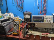
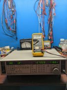
Been reading all week about impedance and seems straightforward. Fired up my new to me very cheap Panasonic signal generator to provide a signal to measure preamp output impedance and ran into a issue.
As I increase amplitude I don't see any AC but do see DC. I'm thinking the output transistor is shorted. Going to open it up and take a look.
As I increase amplitude I don't see any AC but do see DC. I'm thinking the output transistor is shorted. Going to open it up and take a look.
Attachments
R
It’s your test equipment
Rule#1Been reading all week about impedance and seems straightforward. Fired up my new to me very cheap Panasonic signal generator to provide a signal to measure preamp output impedance and ran into a issue.
As I increase amplitude I don't see any AC but do see DC. I'm thinking the output transistor is shorted. Going to open it up and take a look.
It’s your test equipment
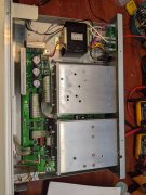
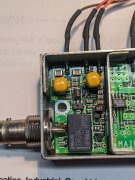
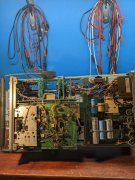
Unfortunately it's all surface mount. Found a schematic and zeroed in on the RF module that is directly at the BNC out connecter. There are two surface mount transistors just to the right of a relay.
Per the schematic these are the "driver and final" and from what I've read, easily shorted with the test cable.
Would really like to test them out of circuit, but given they're surface mount, probably best to just replace them and hope for the best.
Going to take a lot of precision work to get the module apart so I can get to them without damaging other components. Think I'll mix some ChipQuick into the joints before I pull them with tweezers. Bummer. Oh well, another project!
Attachments
Unfortunately it's all surface mount. Found a schematic and zeroed in on the RF module that is directly at the BNC out connecter. There are two surface mount transistors just to the right of a relay.
Per the schematic these are the "driver and final" and from what I've read, easily shorted with the test cable.
Would really like to test them out of circuit, but given they're surface mount, probably best to just replace them and hope for the best.
Going to take a lot of precision work to get the module apart so I can get to them without damaging other components. Think I'll mix some ChipQuick into the joints before I pull them with tweezers. Bummer. Oh well, another project!
Aren't you planning on tracing out signal paths with your scope before you begin shot gunning things?
Scope quit working last weekend. Think one of those weird minature 4 legged rectifiers died.Aren't you planning on tracing out signal paths with your scope before you begin shot gunning things?
Would make better sense to get it up and running as I have a extra power supply for it.
Will do. Going to clear off the bench and fix the scope first. Thanks for keeping me straight.
Scope quit working last weekend. Think one of those weird minature 4 legged rectifiers died.
Would make better sense to get it up and running as I have a extra power supply for it.
Will do. Going to clear off the bench and fix the scope first. Thanks for keeping me straight.
Makes more sense to get that working first George. The scope is your eyes and ears...
At this stage it's apparent I needed a new digital oscilloscope to replace and repair the old HP when I get around to it later.
Been putting this off for a long time. Went up to Microcenter in Cleveland and got a new Siglent
Set the box down in my work room and turned the work room system on not noticing the preamp volume was turned up. The turn on thump blew something out in the preamp. ********* it! The amp is a old bipolar output power amp from the early 70s.
So here I am tracing signal . Funny how things often work out.