gene french
Veteran and General Yakker
- Joined
- Mar 6, 2022
- Messages
- 5,892
- Tagline
- music...the healer of souls...
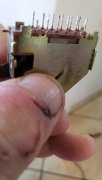
i saw a wire or something under tape mon2 switch...
dont know what it is...
time to take out the switch???
see underneath??
see why pins aint connecting??in down position???
dont know what it is...
time to take out the switch???
see underneath??
see why pins aint connecting??in down position???