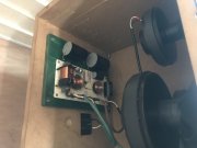
New build for shop system

7.5’^3 should work fine with these drivers. Just have to port accordingly. I went with 10^3 as the response was slightly flatter but it’s was really splitting hairs and I had the room... I’ll let you know my honest opinion when I get these done for sure. If they’re junk, you’ll know it!
 
I think today is crossover day... two nights ago the “speaker lubricant” was flowing and the volume was at 11. I had a welding repair job for a friend yesterday and put the tunes on, quiet. No tweeters left channel... I’ve had trouble with these crossovers and hope it’s not the drivers themselves. I haven’t had trouble with them since I went with two 16 ohm tweeters in parallel. Diaphragm kits are available for them so not a big deal but will have to order them in
 
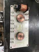
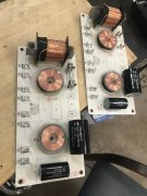
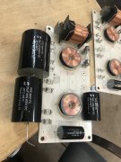
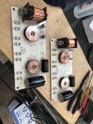
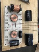
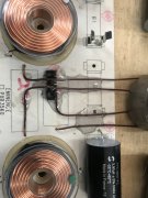
Desoldered two crossovers and reassembling. The HF caps fit on the board nice. Now I have to decide how to mount these big bastards. I’m thinking mount the crossover to a piece of plywood and run wires to the caps. Routing the wires nicely will be a bit of a pain. I have some magnet wire that’s basically the same gauge as the cap leads. I’m thinking to route that along the board, pot it in with epoxy then lay the next wires and pot them. Basically they have to cross each other at some point and I don’t want them to short... yes or no? Anyone see a better/neater way to do this?
 

Attachments

  • 92008870-D333-4AA6-BF64-E1D889AC9906.jpeg
    92008870-D333-4AA6-BF64-E1D889AC9906.jpeg
    1.6 MB · Views: 7
  • 214D1909-DF56-417E-83F0-D9F8582826B2.jpeg
    214D1909-DF56-417E-83F0-D9F8582826B2.jpeg
    1.5 MB · Views: 7
  • 0C9AAC7A-1B68-4609-BA9D-1EF448D44F14.jpeg
    0C9AAC7A-1B68-4609-BA9D-1EF448D44F14.jpeg
    1.4 MB · Views: 7
Son of a bitch. I need another coffee. Put the caps in wrong place :rolleyes:
 
Fixed
 

Attachments

  • D6A50321-811B-456C-9493-9F60F8A3B60C.jpeg
    D6A50321-811B-456C-9493-9F60F8A3B60C.jpeg
    1.6 MB · Views: 4
If you have to cross wires do it at right angles...
Inductors are laid out so their electro magnetic fields do not interfere with one another. Route wires around them that are not going to them..
 
Andrew, if you lay the two big caps side by side are they wider than the board ?
I would build a 2nd board for those and mount it above the original board on stand offs, then take the leads along the bottom of the top board and go straight down when the align with the original holes.
 
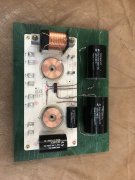
That’s right Lee C1&C2 will be mounted off the board. Here’s what I came up with. Put a little plastic spacer to keep wires separated and cover with 5 min epoxy.
 

Attachments

  • 239F5BA7-13B1-480B-A5D3-F92F097DC8CA.jpeg
    239F5BA7-13B1-480B-A5D3-F92F097DC8CA.jpeg
    1.6 MB · Views: 6
  • C361C370-CDCF-4CFE-AA71-15AAAE4411B3.jpeg
    C361C370-CDCF-4CFE-AA71-15AAAE4411B3.jpeg
    1.5 MB · Views: 6
Andrew, if you lay the two big caps side by side are they wider than the board ?
I would build a 2nd board for those and mount it above the original board on stand offs, then take the leads along the bottom of the top board and go straight down when the align with the original holes.
Well damn... that’s a good idea
 
You could drill some 1/4" holes and use zip ties to attach the caps at the edge of the board maybe...
 
That might get ugly as the board is copper clad on the back. Might tear if you drill through it.
 
Sneak up on the hole size. Start with 1/16 and step through the index to the final size. That should give you a clean hole. Also, drill from the un-clad side, as the bit pulls material up, against the board- drilling on the clad side will pull the cladding off.
 
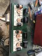
Here’s what i came up with using what I had on hand. I’ll be doing two sets, next set I think I’ll make stand offs and mount them above. Maybe rework these one at that time. The caps are glued down with epoxy.
 

Attachments

  • 1D42F344-948F-4AB3-AE26-9358C6A8B2C1.jpeg
    1D42F344-948F-4AB3-AE26-9358C6A8B2C1.jpeg
    2 MB · Views: 10
  • Like
Reactions: J!m
Installed one just now. Sounds good. Tweeters were ok, bad connection. There were loose solder joints on the spade terminals. I reflowed them.
 
Forgot pics
 

Attachments

  • 006F1FDF-8B25-4257-89EB-F7CBA6A82616.jpeg
    006F1FDF-8B25-4257-89EB-F7CBA6A82616.jpeg
    1.9 MB · Views: 7
  • DC3FA6FC-36A0-4DD0-B76D-CDE05415A925.jpeg
    DC3FA6FC-36A0-4DD0-B76D-CDE05415A925.jpeg
    1.8 MB · Views: 8
Bad mid range speaker right side, kinda knew about that and have replacements on hand. I think the crossover failing toasted it. These three way cabs are going to get a work over also. Plan to front mount the drivers and make trim rings. Enough of this shit for now, heading over to a friends shop to play carpenter for a few hours now. Going to start the big cabinets tonight.
 
Back
Top