No impact...View attachment 59364
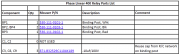
One thing I JUST noticed on the relay board is in my previous build, (shown) I left C3 in place. On THIS board, it appears to be missing from the circuit. Any correlation to what's happening?

You are using an out of date browser. It may not display this or other websites correctly.
You should upgrade or use an alternative browser.
You should upgrade or use an alternative browser.
My Father's Continuing Saga........
- Thread starter Phase Linear Phanatic
- Start date
Phase Linear Phanatic
Chief Journeyman
- Joined
- May 26, 2013
- Messages
- 713
- Location
- St. Louis, MO.
- Tagline
- Born and Raised In The 700 Watt Club.
Are you thinking that it has nothing to do with it as it was related to the Zoebel Network and we don't need that anyway due to the White Oak boards providing the network?
I didn't see a circuit diagram in Don's installation procedures, only a BOM. Perhaps one is provided if you buy it and are assembling it but that wasn't ME. So C3 may have nothing to do with it as C3, C8 and C9 are unpopulated. That lines up with the BOM. All I am looking for are differences between a working amp and a malfunctioning one, and like George did, I left C3 there last time and no issues. Just trying to narrow the possibilities down....

I didn't see a circuit diagram in Don's installation procedures, only a BOM. Perhaps one is provided if you buy it and are assembling it but that wasn't ME. So C3 may have nothing to do with it as C3, C8 and C9 are unpopulated. That lines up with the BOM. All I am looking for are differences between a working amp and a malfunctioning one, and like George did, I left C3 there last time and no issues. Just trying to narrow the possibilities down....
Attachments
Phase Linear Phanatic
Chief Journeyman
- Joined
- May 26, 2013
- Messages
- 713
- Location
- St. Louis, MO.
- Tagline
- Born and Raised In The 700 Watt Club.
Understood....No impact...
C3 should be installed but has no impact on the issues you are reporting. C8 and C9 are the capacitors that are in series with the Zoebel resistors and also have no effect if left in as long as R1 and R2 are not installed.Are you thinking that it has nothing to do with it as it was related to the Zoebel Network and we don't need that anyway due to the White Oak boards providing the network?
I didn't see a circuit diagram in Don's installation procedures, only a BOM. Perhaps one is provided if you buy it and are assembling it but that wasn't ME. So C3 may have nothing to do with it as C3, C8 and C9 are unpopulated. That lines up with the BOM. All I am looking for are differences between a working amp and a malfunctioning one, and like George did, I left C3 there last time and no issues. Just trying to narrow the possibilities down....
View attachment 59366
That meter turn off is normal WITH NO SPEAKERS attached and in the most sensitive meter setting. If you had speakers attached, which you don't because the DCP disconnects them, they would not do that. I have no DCP installed and can simulate that behavior if I disconnect the speakers. It does no harm one way or another. Once I connect the speaker load, that goes away.
Since you have a DCP installed, move your meter feed wires to the output of the DCP and you will have zero meter movement unless the DCP has kicked in.
Since you have a DCP installed, move your meter feed wires to the output of the DCP and you will have zero meter movement unless the DCP has kicked in.
Phase Linear Phanatic
Chief Journeyman
- Joined
- May 26, 2013
- Messages
- 713
- Location
- St. Louis, MO.
- Tagline
- Born and Raised In The 700 Watt Club.
Okay. Sorry for the late reply. Just got done talking to both Mark and my father. As in "What would you like me to do"? I get moving the Meter wires to the binding posts subverts the issue. But it doesn't help explain to me WHY the issue exists at all in the first place when that's how I wired it last time (to the backplanes) and the meters do not do that on that amp? Still........If that's what I have to do, I'll do it. Second, it probably will not solve the low hum. Keeping in mind hum in the speakers are present at zero volume with or without RCA's connected. It is not audible at listening levels. But still again.........this also was not an issue in the last build. The meter swings happen with NO load AND with a load. Having anything at the binding area changes nothing.
Currently i just have two 6ohm bookshelf speakers on the test bench to test. I would like to move it to the big giant speaker system the 700B's are on to see if that hum is also audible through those. Maybe it won't bother him? But with OCD.............these things still irk me. Can't say I'll lose sleep over it, but still..... I don't like building things that have issues with band-aids over them. It gnaws at the OCD. I'd like to know the WHY. More than likely though, the explanation for WHY would probably go right over my head so to keep things easy on everyone, I'll just move the wires.")
To allow critique and criticism on this build, I provide some pics below.


Currently i just have two 6ohm bookshelf speakers on the test bench to test. I would like to move it to the big giant speaker system the 700B's are on to see if that hum is also audible through those. Maybe it won't bother him? But with OCD.............these things still irk me. Can't say I'll lose sleep over it, but still..... I don't like building things that have issues with band-aids over them. It gnaws at the OCD. I'd like to know the WHY. More than likely though, the explanation for WHY would probably go right over my head so to keep things easy on everyone, I'll just move the wires.
To allow critique and criticism on this build, I provide some pics below.
Phase Linear Phanatic
Chief Journeyman
- Joined
- May 26, 2013
- Messages
- 713
- Location
- St. Louis, MO.
- Tagline
- Born and Raised In The 700 Watt Club.
C3 should be installed but has no impact on the issues you are reporting. C8 and C9 are the capacitors that are in series with the Zoebel resistors and also have no effect if left in as long as R1 and R2 are not installed.
My apologies for mis-speaking. C3 is where it's supposed to be!.................. guess i'm trippin on some serious stuff?

Something of Note but probably NOT related, yesterday the Black Wire that goes from the backplane to the driver board had come lose. Too much pullin on it by me. It not being there was pegging my right channel needle. All is well now that I fixed that. Second, I got no sound from that same channel, only to find that the right DC wire from the backplane was in the phoenix hole on the DCP but I hadn't stripped it and connected it. Bonehead rookie mistakes. I fixed THAT and now all seemed to be well. Now I was just left with the meters swinging at ON/OFF and the low hum.
I presume I did no damage in either scenerio when the amp was in a powered on state? (hopefully not) that could have led me to these two remaining issues? I doubt it, but I felt it worth mentioning rather than not and we may come to find out I damaged something? After those two things yesterday, I called it a night. I Didn't want to make anymore mistakes. "One step forward, two steps back" and all that jazz..........
- Joined
- Jan 14, 2011
- Messages
- 75,873
- Location
- Gillette, Wyo.
- Tagline
- Halfbiass...Electron Herder and Backass Woof
The black wire was - DC feed to the board, that didn't hurt anything..
What is your meter telling you for noise on the Speaker outs?
What is your meter telling you for noise on the Speaker outs?
Dave, do you have the nylon insulating washers on both sides of the control board mount studs/long screws? Looks like KEPs nuts, ground loop, hum, if that solder pad is continuous with the boards ground plane. Would check mine, but on the road working. The other guys would know.
- Joined
- Jan 14, 2011
- Messages
- 75,873
- Location
- Gillette, Wyo.
- Tagline
- Halfbiass...Electron Herder and Backass Woof
There is no continuity between those solder pad on the hold down screw holes, but , wounding them will allow a path for corrosion in the inner layers of the board.
Phase Linear Phanatic
Chief Journeyman
- Joined
- May 26, 2013
- Messages
- 713
- Location
- St. Louis, MO.
- Tagline
- Born and Raised In The 700 Watt Club.
You know George, I thought about that today too. In fact I might have used em in the last build. Remember a lot of my work emulates yours. I did NOT use them here. But I looked at the driver board and it doesn't look like those two spots trace anywhere so I thought "nawwww couldn't be that"? Could it? Lemme try that however......please stand by......Dave, do you have the nylon insulating washers on both sides of the control board mount studs/long screws? Looks like KEPs nuts, ground loop, hum, if that solder pad is continuous with the boards ground plane. Would check mine, but on the road working. The other guys would know.
Phase Linear Phanatic
Chief Journeyman
- Joined
- May 26, 2013
- Messages
- 713
- Location
- St. Louis, MO.
- Tagline
- Born and Raised In The 700 Watt Club.
Measure 0 Volts at both outs. If you want to count 4.5mV, well that's about what I did get at them "technically".........The black wire was - DC feed to the board, that didn't hurt anything..
What is your meter telling you for noise on the Speaker outs?
- Joined
- Jan 14, 2011
- Messages
- 75,873
- Location
- Gillette, Wyo.
- Tagline
- Halfbiass...Electron Herder and Backass Woof
4.5 mv is a very noisy 400...
Phase Linear Phanatic
Chief Journeyman
- Joined
- May 26, 2013
- Messages
- 713
- Location
- St. Louis, MO.
- Tagline
- Born and Raised In The 700 Watt Club.
Agreed. Tried the nylon washers as George suggested, no change in hum. Meters still dance. So that 's not what's causing it....
If it was mine, I'd pull the DCP and temporarily tack the flying yellow and ground wires to the speaker jacks. Then retest. If no success, then pull the control board and carefully inspect each component for proper polarity and touch up any questionable solder joints. Then retest. If no success, then pull the back planes, etc. Yes I know bummer.
Also, are you using the original fuse holders? I think the originals for the B+ and B- rails are what, AGX? Have they been replaced with AGC? The original holders take a slightly shorter fuse then the AGC holders do. That shorter fuse in a AGC holder will cause issues.
Also, that solder joint at the wire from the thermo breaker to the transformer. If I remember correctly on my 400 S1, that transformer wire was a solid wire with enamel that needed sanded off and paste flux to get a good joint along with extra heat. Those can look well soldered but not be. That was the toughest joint in the build but I had success once I got it totally clean and fluxed.
Phase Linear Phanatic
Chief Journeyman
- Joined
- May 26, 2013
- Messages
- 713
- Location
- St. Louis, MO.
- Tagline
- Born and Raised In The 700 Watt Club.
Alright so Joe gave me a laundry list of things to try. I made all of them. Obviously the meter issue was solved by moving the wires to the DCP binding posts. (Again, didn't have to do that in the last build and had no issues) but that's what I did. So solved that issue. The hum is still there even after re-routing the way Joe directed me to. Lucky I bought 2 wire kits when I only needed one. Allowing myself the extra wire need to make these modifications.
So I had my father bring my other build to me today. He was over here watching me make the changes. I did NOT make the changes to the meters on the one he brought. He said a big flat NO to that. Doesn't want to mess with something that works. So I used it to look at my own work from last year and sure enough, all was the SAME as what I just wired on THIS amp. So No wiring departures on my part. I hooked that other amp up and also heard the hum. Both builds had it. But only if you put your ear literally up to the speaker. Otherwise it's inaudible. I guess it went un-noticed in my last build? Either way, my father just said "not a big deal, I can't hear it from across the room anyway" and since both do it, he was willing to live with it.
We tested it on my PL700B system. Swapped one of the 700B's out on the highs with the 400 since he's bi-amped and that's what it's gonna be driving. It Jammed perfectly. Attenuation switch worked same as the other amp so all is now solid. It just bugs me that I didn't have that meter issue on that last build and those went right to the backplanes but this one did? Owell. It 's fixed and it works. I sent him home with both amps as he was happy and that's all that matters.
I personally preferred the look of the wire routing in my last build to this one. Namely because I had less 'bundles' run but here I made more just to separate AC and DC more effectively. Doing so changed nothing sonically, but made for a less appeasing wire job to an OCD guy like myself.
Below are some pics I took before I sent him home with the goods. The FIRST pic is the old build. It has Joes blue/purple/white pigtails for the attenuation switch. The others are the current build. I'm not sure how comfortable I'd feel doing a 700B build after all this? Might be awhile yet. But when I do, it won't be for someone as important as my father. So I'll be doing ALL the board population myself. We'll see how that goes when the time comes. I have 12 amps to do sooooo the funds will come from my retirement account probably and that's not too far in the distant future. Thanks for everyone's help on this!
- Joined
- Jan 14, 2011
- Messages
- 75,873
- Location
- Gillette, Wyo.
- Tagline
- Halfbiass...Electron Herder and Backass Woof
Looking good Dave!!
You can fix your OCD concern by running the red and white wire from the DCP to the meter board laced to your grey ground wires and over to the meter board. likewise for the black ground wire coming in from the left, it can be routed with the other grey ground wires and over to the meter board. The central orientation applied to when you were running them from the backplane boards. But you have moved them.Alright so Joe gave me a laundry list of things to try. I made all of them. Obviously the meter issue was solved by moving the wires to the DCP binding posts. (Again, didn't have to do that in the last build and had no issues) but that's what I did. So solved that issue. The hum is still there even after re-routing the way Joe directed me to. Lucky I bought 2 wire kits when I only needed one. Allowing myself the extra wire need to make these modifications.
So I had my father bring my other build to me today. He was over here watching me make the changes. I did NOT make the changes to the meters on the one he brought. He said a big flat NO to that. Doesn't want to mess with something that works. So I used it to look at my own work from last year and sure enough, all was the SAME as what I just wired on THIS amp. So No wiring departures on my part. I hooked that other amp up and also heard the hum. Both builds had it. But only if you put your ear literally up to the speaker. Otherwise it's inaudible. I guess it went un-noticed in my last build? Either way, my father just said "not a big deal, I can't hear it from across the room anyway" and since both do it, he was willing to live with it.
We tested it on my PL700B system. Swapped one of the 700B's out on the highs with the 400 since he's bi-amped and that's what it's gonna be driving. It Jammed perfectly. Attenuation switch worked same as the other amp so all is now solid. It just bugs me that I didn't have that meter issue on that last build and those went right to the backplanes but this one did? Owell. It 's fixed and it works. I sent him home with both amps as he was happy and that's all that matters.
I personally preferred the look of the wire routing in my last build to this one. Namely because I had less 'bundles' run but here I made more just to separate AC and DC more effectively. Doing so changed nothing sonically, but made for a less appeasing wire job to an OCD guy like myself.
Below are some pics I took before I sent him home with the goods. The FIRST pic is the old build. It has Joes blue/purple/white pigtails for the attenuation switch. The others are the current build. I'm not sure how comfortable I'd feel doing a 700B build after all this? Might be awhile yet. But when I do, it won't be for someone as important as my father. So I'll be doing ALL the board population myself. We'll see how that goes when the time comes. I have 12 amps to do sooooo the funds will come from my retirement account probably and that's not too far in the distant future. Thanks for everyone's help on this!
View attachment 59431
View attachment 59432
J!m
Veteran and General Yakker
I like stuffing boards. It’s sort of zen or something. Like working on an eight billion piece jigsaw puzzle. Oddly satisfying.
Phase Linear Phanatic
Chief Journeyman
- Joined
- May 26, 2013
- Messages
- 713
- Location
- St. Louis, MO.
- Tagline
- Born and Raised In The 700 Watt Club.
Thanks Lee! And Joe! i TRY to do the best work I can to my abilities. (Though they be limited). It was a joyous moment to send my dad home packing two powerful full-montied WOPL400's. I loaded them into his van and told him to enjoy them as he drove off into the sunset. He will be hooking them both back in-line tommorrow. I told him to call me and let me know how it sounds. He was ecstatic as it was.Looking good Dave!!
And this is all from a guy who started out this saga by saying "I'm not paying x amount of dollars for something I've never heard before"? So I spent it for him initially because I already knew it was worth it. (He paid it back later and I told him not to but he insisted). Never did I think he'd do it a SECOND time! He's a convert for sure and I am glad we have this group of guys here to help each other out. You've saved my ass more than a few times to say the least.
By the way........He READS these posts. So everyone say hi to Bill.