WOPL Sniffer
Veteran and General Yakker
I guess I'm wondering about the backplane.... use the old shit from P L, or use Joe's good backplane?

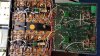
That will fit with DCP board.The new PLX driver board is slightly larger than the original PL36. The PLX is 8.25" x 5.75". The original Pl36 is about 6 3/4" x 5 5/8".
The PLX will fit into 400 and 700 chassis, but I'll have to double check fitting both the PLX and a DCP. I just thought about how popular the DCP is just now.
The PLX is all one board.
Nick I emailed you better photos for you to look atThanks Glen for confirming that.
I tried to keep the PLX the same size as the original PL36, but there were just too many components in the new design to use the same size PCB and have room to comfortably layout the components without the PCB being "densely populated".
Sniffer,
The PLX will work with the WO backplane. I will make sure the documentation for the PLX clearly covers all the connections points, what they do and where they need to be connected.
I am going to order boards for my new PL amp design soon. I need 15 for my heard.
Preliminary Specs (Will be finalized when PCB's come in and testing begins)
- 100kHz power bandwidth (I don't recommend trying to get 350 Watts out at 100kHz, but it should do it, in theory)
- Slew rate - 37 V/us (Calculated. In reality, closer to 33 V/us probably)
- >100dB signal to noise
- THD+N at 20kHz <0.002% at 350 Watts/8 Ohm
- 1 Watt frequency response - 0.5Hz ~ 200kHz
Low distortion and slew rate are not everything and the design will be tweaked for sound quality and stability as well. To my ears, if an amp is "too fast" (high slew rate), it sound cold and clinical (not warm/musical). However, since we all hear differently, this design can be easily manipulated for your listening preference(s) within reasonable limits.
Let me know if you want to participate in the PCB order, so I can get an order quantity going. It looks like unstuffed PCB's will be $64 shipped in the contiguous US.
Except for some capacitor values/types, the "amp control board" design is very forgiving and parts selection is not too critical. The drivers and outputs for a full comp version should still use MJ15024/25 or MJ21195/96 transistors.
Board features will include:
- FR-4 epoxy glass board
- Top and bottom solder mask
- Top silk printing (white)
- RoHS compliant
- Double-sided, plated through holes
Just curious; Do you have your boards made here in the states or overseas?
Nick,
Thanks for offering up some specs on your board.
Is the S/N ratio unweighted or A weighted or perhaps DIN (Audio) flat from 22-22kHz?
Is the power bandwidth (essentially) flat all the way out to 100 kHz or 3dB down at 100kHz?
Any ideas on what channel separation is at 1KHz, or 10 kHZ, or 20 KHz at rated output or at -3dB?
How about damping factor (at a given frequency)?
Phase Shift?
Rise Time?
Thanks again!
Ed
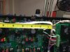
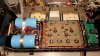
I have "grafted" the latest 400-700 driver circuit onto one of my PL36 PCB's and installed a DCP (Thanks to Glen for sending an extra he had).
Before I order the PCB's, I want to get a second opinion of the amp performance, so I am sending the entire amp to Glen for his evaluation. I am getting 400 Watts out at 1kHz @ 0.2% THD+N.
The circuit is capable of better (distortion) performance than what the PL 400-700 chassis will allow. In other words, the 400-700 heat sink area is not large enough to bias the amp to the optimum setting without the heat sink getting very warm at idle. I knew this was going to be a limitation and was prepared to work within the limits of the PL chassis. This mainly affects the 20kHz THD+N. However, I have found a compromise setting and I am happy with it.
Test results of unit being sent to Glen:
Frequency Response @ 1 Watt/8 Ohm: 0.5Hz to 250kHz
Frequency Response @ 50 Watts/8 Ohm: 0.5Hz to 250kHz
Signal to Noise (Inputs grounded): <200uV's
Rise Time: 1.4uS
Slew Rate: 45V/uS
THD+N @ 1 Watt/1kHz: 0.015%
THD+N @ 1 Watt/20kHz: 0.06%
Phase Response: +3° @ 10Hz, -5° @ 20kHz
Left Channel Separation: 1kHz/80dB, 10kHz/67dB, 20kHz/63dB
Right Channel Separation: 1kHz/75dB, 10kHz/70dB, 20kHz/68dB
Have not measured damping factor. It should be the same as the PL spec since the output stage has not changed.
Ed,
The circuit is being debugged/tested before I get the PCB's made, so yes, the final PCB is coming.
I'll post more detailed test info later.
Frequency response is referenced to 0dB with 1kHz as the reference.
On this amp, I have bypassed the level controls. I never use them (on any amp) and they just get in the way (literally and from a noise stand-point). I'm sure somebody may have a need for them, but I don't.
THD+N @ 20kHz full power will be posted tonight after more testing.
Channel separation was done at 1 Watt, but I can do other levels too. Let me know the exact power levels you are interested in (1, 50, 200 or 350 watts, etc).
That's a lot of power bandwidth!
Interesting thread. I'd like to hear some feedback on how it sounds compared to an amp with the WO boards. Test results are really good to have but gotta do the ear test.
So this amp has the same power output at every frequency between .5 Hz and 250k hz?? That's what you are infering by not putting a plus or minus db figure at each extreme...