Fully Discrete 400 / 700 Driver Circuit (Full Comp Only)

THD+N

Journeyman
Joined
Dec 10, 2012
Messages
139
#1
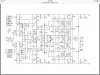
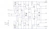
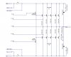
I have finally had a chance to design a new driver circuit for the 400 and 700. The 400 and 700 make excellent project amps because of the way the chassis is laid out and the power transformers are robust. The latest power supply caps pack more Farads, so updating to more capacitance is easy in the space allotted. I've wanted to use a 400 or 700 chassis with a new driver circuit for awhile now. No output relay protection is included (yet). I'll work on that last.

A few sample boards are being completed to test and debug the circuit. Once the bugs are worked out, I will begin the final PCB layout. I'm going to offer bare PCB's for sale, but have no intention of offering "stuffed" PCB's. This is only a hobby for me and not my main source of income.

The design is based on currently available transistors that should be easy to source for the near future. Due to the design, a wide variety of transistors can be used with slight variance in performance.

With the exception of using a 400 or 700 power supply and chassis, the "new amp" will not be a Phase Linear.

Phase Linear 400-700 PLX_New Driver Board_Initial Design_v1.1_071417.jpg Phase Linear 700 PLX_New Driver Design_Output Section_v1.1_071417.jpg
 

THD+N

Journeyman
Joined
Dec 10, 2012
Messages
139
#3
Probable not. It may be better. It may not be. From a technical standpoint the design will address distortion mechanisms that have been identified and documented (Cordell, Self and Slone). Noise and distortion will be low, but we all know that that doesn't really mean anything when it comes to personal preference and listening. We all hear in a different manner.

In my opinion, a few items that define the "Phase Linear" sound are;
  1. Class B output biasing
  2. Triple output stage configuration
  3. High voltage (compared to other amps in the early 70's) unregulated power supply
  4. And finally, to some extent, the front-end driver circuitry

The Phase Linear output stage (either quasi or full comp) is the easiest part of the amp to modify for best performance. If configured properly, the quasi-comp can offer good performance (as we Phase Linear lovers all know), but a full comp output stage is so easy to implement today there is no reason to not make the conversion. My ears appear to be extremely sensitive to crossover distortion, so I prefer Class A amps or Class B amps that are properly designed and biased.

If you build the circuit and it is too "sterile", I suppose you could always bias (true Class B) the output stage similar to a standard Phase Linear 400 or 700. It's all part of the fun.
 

Northwinds

Veteran and General Yakker
Joined
Mar 18, 2013
Messages
7,546
Location
Coventry, CT
Tagline
Fondler errrr... fan of all Nav's avatars
#4
I am pretty sure Joe addressed all those issues with the White Oak line of componentry, are you offering something better??? It would have to be damn good to even touch a FC WOPL
 

THD+N

Journeyman
Joined
Dec 10, 2012
Messages
139
#5
Joe's design and my design are totally different. Joe's design is similar to the original PL circuit. Mine is not.

My design offering is not meant to be a "competition", it's an alternative. In the end, when the PCB is available and you want to try it, great. If not, I'll still be tinkering with different designs and offering them to DIYer's.
 

THD+N

Journeyman
Joined
Dec 10, 2012
Messages
139
#7
Each stage (input stage, VAS stage and output stage) is optimized / linearized with local feedback (degeneration), then global feedback is used. Since each stage is operating in a very linear manner, minimal global feedback is needed. I prefer to keep a design a simple as possible and not use esoteric type designs. I also like the amp to be easily serviced, if needed.

In the design I posted, the input stage is degenerated to improve linearity and slew rate. The VAS stage is isolated from the input stage via an emitter follower which also increases linearity. The feedback capacitor (Cdom) across the emitter follower/VAS is the only cap needed for stability (usually). The triple OPS lightly loads the VAS, which also increases linearity. In the end, you only need a moderate amount of global feedback to reduce distortion.

Audio amp design used to be a considered a "black art", but with people willing to share knowledge such as Self, Slone and Cordell (and others) amp design has been broken down to a systematic approach. If you follow their design methodology, it is very easy to design a reliable, stable excellent sounding amplifier. A lot of design derivations are possible with great performance. It just depends on the individual and how the amp will be used.

Don't get me wrong, low noise and distortion is not everything. I still design and build (low power) Class A tube amps! If it amplifies, I will more than likely be intrigued by it.
 

Northwinds

Veteran and General Yakker
Joined
Mar 18, 2013
Messages
7,546
Location
Coventry, CT
Tagline
Fondler errrr... fan of all Nav's avatars
#9
Joe's design and my design are totally different. Joe's design is similar to the original PL circuit. Mine is not.

My design offering is not meant to be a "competition", it's an alternative. In the end, when the PCB is available and you want to try it, great. If not, I'll still be tinkering with different designs and offering them to DIYer's.
I would give it a whirl, is it a drop in replacement or is a major overhaul needed with an already made WOPL (out of curiosity)
 

krellmk

Chief Journeyman
Joined
Nov 3, 2016
Messages
705
Location
Brooklyn NY
Tagline
Are you satisfied with the life you're living
#10
Leach super amp

Isn't this design similar to the Leach Super amp and the Low tim amp?
 

grapplesaw

Veteran and General Yakker
Joined
Aug 13, 2014
Messages
2,765
Location
Vancouver
Tagline
---
#11

Attachments

Last edited:

THD+N

Journeyman
Joined
Dec 10, 2012
Messages
139
#12
The Leach DB design used stacked output transistors to increase power output. The "stacking" (a variation of cascoding) also allowed the use of transistors with a lower voltage rating.

However, to answer your question, the design I am working on is not the same as the Leach. The Leach design does not use any current mirrors in the input stage nor is the VAS buffered with an emitter follower.

I've never heard a Leach Amp, but I understand they sound very good. I have a few AB International 600LX's, which are similar to the Leach, and the 600LX sounds pretty good.

I'm not really a MOSFET person. I've tinkered with a few basic designs, but always come back to BJT's.
 

THD+N

Journeyman
Joined
Dec 10, 2012
Messages
139
#14
Is a major overhaul needed with an already made WOPL (out of curiosity)
My intention is to make the new PCB the same dimensions as the original PL36 board with connections at the bottom. The only modification will be to the 150 Ohm pre-driver and 10 Ohm driver resistors.

The 150 Ohm resistors can be removed because the new PCB will include the pre-driver resistor (one resistor is shared between the 2 pre-drivers). The two 10 Ohm resistors can be replaced by two 18 Ohm resistors or a single 36 Ohm resistor.
 

Gibsonian

Chief Journeyman
Joined
Aug 3, 2011
Messages
783
#15
I'd be interested in trying this out on a spare PL700 series I have just sitting there on the shelf. Please keep us posted.
 

THD+N

Journeyman
Joined
Dec 10, 2012
Messages
139
#16
After tossing the new amp idea around for awhile and considering the 400 and 700 chassis layout, I have finalized the amp design. It's not the one I was anticipating originally, but it is a good design (tried and true) and should offer exceptional performance from a 400 or 700 chassis.

The amp design is a classic Lin topology with current mirrors. I have added a cascode to the input stage, so I can experiment with different low noise input transistors. The VAS is buffered from the input stage as well as sharing the current source. A lot of decoupling has been implemented so the triple emitter follower (EF3) is stable with no tendency to oscillate. Because of the way the current source is configured, there should be no turn-on/off thumb or pops.

See schematic and layout below;


View attachment PLX400-700PLX Schematic_Web Version__112017.pdf View attachment PLX400-700PLX PCB Layout Front_112017.pdf View attachment PLX400-700PLX PCB Layout Back_112017.pdf

I am proofing the layout now, and hopefully, I'll have some boards ready for testing soon.
 

WOPL Sniffer

Veteran and General Yakker
Joined
Aug 10, 2015
Messages
11,227
Location
Minnie-Soda
Tagline
Screw it
#18
Don't do it Nick, you'll never get off the phone..... LOL

No, seriously, I'd like to do some playing... let me know when they are available,and price. These will fit into a 700B/II chassis and its all 1 board?.... you ginned em up just like that and will bolt right in? I'm impressed. Sometimes I'm loaded, but right now, I'm impressed.
 

THD+N

Journeyman
Joined
Dec 10, 2012
Messages
139
#19
The new PLX driver board is slightly larger than the original PL36. The PLX is 8.25" x 5.75". The original Pl36 is about 6 3/4" x 5 5/8".

The PLX will fit into 400 and 700 chassis, but I'll have to double check fitting both the PLX and a DCP. I just thought about how popular the DCP is just now.

The PLX is all one board.
 
Top