Carver C1 going through rework

Gepetto

Administrator
Staff member
Joined
May 15, 2011
Messages
13,473
Location
Sterling, MA
Tagline
Old 'Arn Enthusiast
Yeah 2 thoughts:

  1. The positive bias to the JFET gate is way positive (as in +10V+) during the time you are seeing the 33 and 23 mV and then switches way negative when you see it go back to the level before power on. It could be leakage from the junction FET gate into the drain terminal. This JFET is being biased hard to an on condition during your 8 second period by IC8 (it only takes 0 V at the gate to turn on a JFET, this design is applying ~+10V).
  2. The ground that the source of each JFET is attached to is really not ground but a ground that is offset by 33 or 23mV from the real ground. This would be a board layout related issue if it is the case. (This is probably unlikely but could exist)
Now that we have a bead on this, what I would recommend is that you increase the value of R261 and R361 from 2.2K to ~100K. Try it on the left channel first which has the worst offset to see if it makes a difference.

If it works, you can call it the Gepetto fix. Otherwise not :)

A MOSFET N-Channel enhancement device may also do a much better job than the current N-channel JFET depletion device that is in there now, but that can be reserved for a future discussion.
 
Last edited:

Gepetto

Administrator
Staff member
Joined
May 15, 2011
Messages
13,473
Location
Sterling, MA
Tagline
Old 'Arn Enthusiast
Note: N channel enhancement mode MOSFETs probably only existed in the lab in the days this preamp was created. JFETs were it in those days.
 

WOPL Sniffer

Veteran and General Yakker
Joined
Aug 10, 2015
Messages
11,223
Location
Minnie-Soda
Tagline
Screw it
If you planned on changing the old 4136's and you "THINK" the FET's are good, I'd change them out first before modifying the circuits. But hey, that's just the way I'd try it first. The current TI issue 4136's won't alter the sound if that's what you were worried about.
 

Mohawk

Chief Journeyman
Joined
Oct 29, 2019
Messages
588
Location
Ontario Canada
Hey Joe, Perry

I just got back to the bench and made a discovery this morning ... If I have the amp on and a CD player playing...
Power off the C1 for 10 seconds or so ... Then power back on the C1 and I hear low level music coming through prior to
IC 8 switching the FETS.... If I quickly adjust the volume during the mute circuit on time I do hear it get louder.... After the fets switch, music is back and everything seems ok....

So what Joe said seems totally plausible to me ....

"Yeah 2 thoughts:"

  1. "The positive bias to the JFET gate is way positive (as in +10V+) during the time you are seeing the 33 and 23 mV and then switches way negative when you see it go back to the level before power on. It could be leakage from the junction FET gate into the drain terminal. This JFET is being biased hard to an on condition during your 8 second period by IC8 (it only takes 0 V at the gate to turn on a JFET, this design is applying ~+10V)"
*"Now that we have a bead on this, what I would recommend is that you increase the value of R261 and R361 from 2.2K to ~100K. Try it on the left channel first which has the worst offset to see if it makes a difference."

I'm gonna' swap out R262 / R361 to 100k and post back !

Thanks !

M
 

Gepetto

Administrator
Staff member
Joined
May 15, 2011
Messages
13,473
Location
Sterling, MA
Tagline
Old 'Arn Enthusiast
JFETs typically don't have very low channel "ON" resistance.
The reason you still hear music playing while muting is for the above reason. It attenuates but does not really mute it altogether. I think the PL manual tells you this.
 

Gepetto

Administrator
Staff member
Joined
May 15, 2011
Messages
13,473
Location
Sterling, MA
Tagline
Old 'Arn Enthusiast
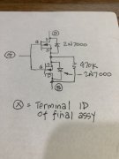
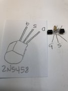
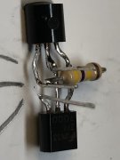
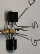
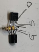
You need to back to back 2 MOSFET devices in an application like this which is why it is complicated.

Pictures show what you have to do. Assembled to hopefully show what you have to do. An 1/8W resistor would have been better but could not readily find one. IMG_2989.jpg
 

Attachments

Last edited:

Gepetto

Administrator
Staff member
Joined
May 15, 2011
Messages
13,473
Location
Sterling, MA
Tagline
Old 'Arn Enthusiast
You have proven to yourself there is no bump noise in the headphones which is driven by this same circuit, the simplest solution is to remove the two 2N5458 JFETs
 

VSAT88

Veteran and General Yakker
Joined
Sep 7, 2017
Messages
1,798
Location
Phenix City Alabama
Tagline
Like my BlueTooth ?
Well, I told you the same thing yesterday. You asked for my "Expertise" and I gave it to you. You can do with it as you like. The first 6 times, I told you nicely, not the second 6.... I'm a jerk, and you are a hard head............. No winner either way
LOL !!!!!!!!!!!!!!!!!!!!!!!
 
Top