400/1 “Linda” Full WOPL

Working on Linda’s backplanes a little this morning. Have to head to the shop take care of a few things this afternoon then back at Linda this evening.
 

Attachments

  • FA6D4B84-BACC-4048-A6A5-680722C6A415.jpeg
    FA6D4B84-BACC-4048-A6A5-680722C6A415.jpeg
    4.1 MB · Views: 16
Finished populating the backplanes. Time to gut the chassis I guess.
 

Attachments

  • 6E2AB56A-CF30-4042-8B17-34C55B6D9442.jpeg
    6E2AB56A-CF30-4042-8B17-34C55B6D9442.jpeg
    1.9 MB · Views: 19
When you wire your backplanes, you have two options. You can "Daisy Chain" them together with short pieces of wire, or wire them "Dual Mono" as in the photo. Also note the green B+ wire that comes off the right top corner of the right backplane. This goes to the DCP as Joe explains in the wiring directions, but easily overlooked. This is best way to run this particular wire, rather than a long run all way back over to the cap.
 

Attachments

  • PXL_20210209_171207262.jpg
    PXL_20210209_171207262.jpg
    3.7 MB · Views: 60
When you wire your backplanes, you have two options. You can "Daisy Chain" them together with short pieces of wire, or wire them "Dual Mono" as in the photo. Also note the green B+ wire that comes off the right top corner of the right backplane. This goes to the DCP as Joe explains in the wiring directions, but easily overlooked. This is best way to run this particular wire, rather than a long run all way back over to the cap.
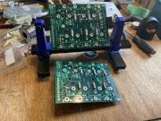
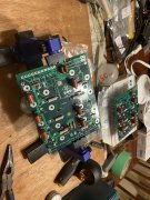
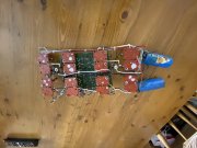
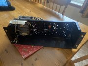
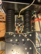
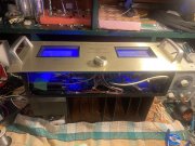
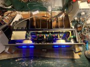
Hey, you got a “Linda” too! Thanks for the heads up. Gonna be lots of reading as I go through the wiring for sure.
 
Also note the green B+ wire that comes off the right top corner of the right backplane. This goes to the DCP
You can check with Don, but I believe the current draw on that wire going to the DCP Board is miniscule. It could easily be a green 22 Ga. wire.

BTW, I like your use of forceps as a soldering heat sink.
 
Gutted Linda this morning. Didn’t even have to desolder the transformer center tap leads from the bus bar. Cold and broken solder joints courtesy of Pete’s Electronics in St. Catharines Ontario, Canada. Same guy who “lost” (cough STOLE cough) my RT-707...

There were only 4 transistor sockets that weren’t broken in this amp... think she’s had a hard go over the years...
 

Attachments

  • 19EAF2D7-3C73-4A85-9546-B1C821C2D90A.jpeg
    19EAF2D7-3C73-4A85-9546-B1C821C2D90A.jpeg
    2.8 MB · Views: 40
  • 52453EF8-F6F8-4075-B686-969AF855C7DA.jpeg
    52453EF8-F6F8-4075-B686-969AF855C7DA.jpeg
    948.1 KB · Views: 41
  • F60E9347-E0AF-4C6A-AD1C-8C575CE93B94.jpeg
    F60E9347-E0AF-4C6A-AD1C-8C575CE93B94.jpeg
    4 MB · Views: 45
  • 6168B146-105A-4195-9984-86F826902011.jpeg
    6168B146-105A-4195-9984-86F826902011.jpeg
    933.5 KB · Views: 44
Started picking at Linda again, put the last four zeners in to complete the board. It’s been a while since I’ve worked at this so I went through the BOM again just to make sure it was complete. Got nervous for a minute as I thought I had made an oopsie but had the BOM mixed up with Tim’s quasi comp... looks like it’s ready other than cleaning now.
 

Attachments

  • 8E72F50B-5E97-4240-997E-B6EE7355DF0C.jpeg
    8E72F50B-5E97-4240-997E-B6EE7355DF0C.jpeg
    3.8 MB · Views: 24
Linda’s coming to life. Passed all tests with drivers installed today. I’m busy and grumpy. I said grumpy, not angry so that’s an improvement...
 

Attachments

  • 59036CD9-0A61-44EE-9B95-8CD7F2910F0E.jpeg
    59036CD9-0A61-44EE-9B95-8CD7F2910F0E.jpeg
    3.3 MB · Views: 19
  • DD35C55E-EE70-4645-94F4-D9CAF15D3322.jpeg
    DD35C55E-EE70-4645-94F4-D9CAF15D3322.jpeg
    3.1 MB · Views: 20
  • BE92C239-02E0-430F-BE0C-77539304E58B.jpeg
    BE92C239-02E0-430F-BE0C-77539304E58B.jpeg
    3.5 MB · Views: 21
  • C76DF60D-DD06-44C6-B4FC-D15E1B90FCE5.jpeg
    C76DF60D-DD06-44C6-B4FC-D15E1B90FCE5.jpeg
    3.2 MB · Views: 25
  • 2EC20FF3-465A-48A8-95CB-29BD3ED9BAB8.jpeg
    2EC20FF3-465A-48A8-95CB-29BD3ED9BAB8.jpeg
    3 MB · Views: 26
  • 527B704F-225A-4BC2-B556-080857F9BCBE.jpeg
    527B704F-225A-4BC2-B556-080857F9BCBE.jpeg
    1.6 MB · Views: 26
  • 5AC9338A-60F1-4DA6-B57E-DB016168833E.jpeg
    5AC9338A-60F1-4DA6-B57E-DB016168833E.jpeg
    1.7 MB · Views: 26
  • 656121DD-A8A7-41DA-9728-BAD929202013.jpeg
    656121DD-A8A7-41DA-9728-BAD929202013.jpeg
    3.6 MB · Views: 25
  • B7E490CB-52A6-4411-A9B0-B31BB7D2F197.jpeg
    B7E490CB-52A6-4411-A9B0-B31BB7D2F197.jpeg
    1.7 MB · Views: 24
She’s alive! No issues getting it together other than having to grind the capacitor hold down plate to clear the meter stud. I’ve got to check my left speaker and crossover. Somethings not right but Tim was acting goofy on the left also so I doubt it the amp. Haven’t listened to her much as I want to run some tests on the left speaker first. There’s no audible hum but if I have her apart again I will reroute some wiring... I already moved the thermal switch wiring but there’s some others could be farther from signal.
 

Attachments

  • 6EB4D50A-61EE-4221-9891-13EEE8B2CD0D.jpeg
    6EB4D50A-61EE-4221-9891-13EEE8B2CD0D.jpeg
    3.1 MB · Views: 12
  • 8FCDB793-43D9-4ED9-A808-EC59EB16683F.jpeg
    8FCDB793-43D9-4ED9-A808-EC59EB16683F.jpeg
    2.5 MB · Views: 12
  • 56115F70-9B89-4EE0-A267-467F73570FEA.jpeg
    56115F70-9B89-4EE0-A267-467F73570FEA.jpeg
    3 MB · Views: 11
  • 4E3CD124-F8AC-4653-A452-94849E6CC41D.jpeg
    4E3CD124-F8AC-4653-A452-94849E6CC41D.jpeg
    3.2 MB · Views: 12
  • EC26EDA9-ADCA-4F89-A1DC-00C7793691FF.jpeg
    EC26EDA9-ADCA-4F89-A1DC-00C7793691FF.jpeg
    4.1 MB · Views: 13
  • 781FBB8C-53AC-4ACB-BE6F-964964C3588F.jpeg
    781FBB8C-53AC-4ACB-BE6F-964964C3588F.jpeg
    3.2 MB · Views: 16
  • 142D2657-49D2-422C-8E46-BB139E3B828B.jpeg
    142D2657-49D2-422C-8E46-BB139E3B828B.jpeg
    2.6 MB · Views: 13
  • 9AE90540-D8F0-4C1E-9469-FC43DFF4814D.jpeg
    9AE90540-D8F0-4C1E-9469-FC43DFF4814D.jpeg
    2.7 MB · Views: 17
  • 754AE3E4-C1B6-47A2-BC5F-3BEE2B1CDC8D.jpeg
    754AE3E4-C1B6-47A2-BC5F-3BEE2B1CDC8D.jpeg
    3 MB · Views: 19
She’s alive! No issues getting it together other than having to grind the capacitor hold down plate to clear the meter stud. I’ve got to check my left speaker and crossover. Somethings not right but Tim was acting goofy on the left also so I doubt it the amp. Haven’t listened to her much as I want to run some tests on the left speaker first. There’s no audible hum but if I have her apart again I will reroute some wiring... I already moved the thermal switch wiring but there’s some others could be farther from signal.
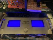
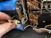
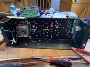
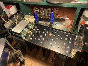
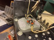
Too late now Andrew but you could have avoided the milling of your hold down plate by mounting the bridge in the recommended rear hole (as pictured on the web page), not the front hole. When mounted in this position, the edge of the hold down plate almost comes in contact with the chassis side wall.
 
Back
Top