400/1 “Linda” Full WOPL

AngrySailor

Veteran and General Yakker
Joined
Oct 15, 2014
Messages
3,419
Tagline
---not quite right
#42
When I was “questionable” age to buy beer, I would ask for “two four, Pee’br. CANS”. (Pabst blue ribbon). All the “kids” wanted brand name beer, they’re not ID’n a guy in work clothes asking for PBR... made my youth easy...
 

AngrySailor

Veteran and General Yakker
Joined
Oct 15, 2014
Messages
3,419
Tagline
---not quite right
#46
Well, time to trim the back of the board, getting hard to reach stuff, my flush cut pliers are out in the shop and it’s freezing raining sideways here... might be enough progress for the night.
 

AngrySailor

Veteran and General Yakker
Joined
Oct 15, 2014
Messages
3,419
Tagline
---not quite right
#48
Linda’s board all done aside from some trimming leads and cleaning. Got worried for a minute when I had unpopulated items then remembered this is full comp, double checked the BOM and we’re all good. Short 4 zeners, but there’s no rush to put them in, I still have to build the back planes and start working on the chassis.
 

Attachments

Last edited:

AngrySailor

Veteran and General Yakker
Joined
Oct 15, 2014
Messages
3,419
Tagline
---not quite right
#50
Sockets installed in one board. Seemed to go ok.

looks like the bias trannies mount directly to the board? I thought I needed P-straps but guess not eh? Haven’t read that far ahead in the destructions yet...
Edit. Nvm, looks like I still be some P-straps...
 

Attachments

Last edited:

George S.

Veteran and General Yakker
Joined
Feb 18, 2020
Messages
4,590
#51
Andrew, yes, your going to need P-straps, they mount to a stud that's mounted to the back wall. I highly recommend you get the optional Phoenix connectors (screw jack connectors), they're listed at the end of the control board BOM if I remember correctly. You'll need 4 of the 3 screw for the bias transistors, and 4 of the long I forget how many screws. These will secure those fine gauge wires securely and allow easy removal of the control board for any future work.
Also a good idea to have a screwdriver or shovel shaped tip for your iron when soldering the PEM nuts to that backplane. On a very old post Joe recommended this tip, spin the PEM nut with the shovel tip while heating and adding solder to get good penetration and a nice meniscus. I spun mine with a screwdriver tip and got good penetration and a nice fillet. There is a huge amount of copper in those backplanes, sucks the heat right out of that iron. Joe's technique makes it easy.
 

mlucitt

Veteran and General Yakker
Joined
Jun 24, 2011
Messages
3,375
Location
Jacksonville, FL
#53
Have I got enough solder on these standoffs? You can just see it sweating through the other side most ways around the socket.
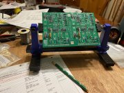
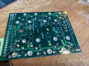
Just make sure they are flat and square to the board otherwise the screws that hold the output transistors in, will be cockeyed.
I use a straightedge to verify squareness across the whole row and a fine file to rub off any solder that might have migrated to the top surface.
 

mlucitt

Veteran and General Yakker
Joined
Jun 24, 2011
Messages
3,375
Location
Jacksonville, FL
#55
I’ll bring a straight edge in from the shop. They seemed to all sit down nice, I was able to give them a spin with the iron tip also.
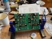
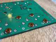
one done.
I used to get one or two PEMs on each board that were slightly tipped and had to reheat them. I am better at it now, with the help of some springs that hold them down under pressure against the socket head screws.
 

George S.

Veteran and General Yakker
Joined
Feb 18, 2020
Messages
4,590
#56
Looks good! And on installing those bias transistors, you"ll really only have one chance to solder them in, so mock up the install with the board mounted. When your satisfied everything is good, carefully tack solder the transistor to the board, remove the board, solder each leg.
If you you mess it up, you'll have to cut the leads, extract each leg individually, probably need hot air and vacuum desoldering, just so much copper there.
 

mlucitt

Veteran and General Yakker
Joined
Jun 24, 2011
Messages
3,375
Location
Jacksonville, FL
#57
And on installing those bias transistors,
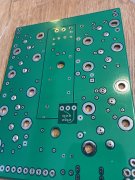
I pre-bend the leads and solder them on the bench to have the P-straps match the silkscreen outline on the board. You just have to make sure they don't protrude too far down below the board. But if you get the bends just right, there is nothing to trim off.
 

AngrySailor

Veteran and General Yakker
Joined
Oct 15, 2014
Messages
3,419
Tagline
---not quite right
#58
That’s done, when I decide to put pants on I’ll get my straight edge and double check them. I’ve got lots of work to do before worrying about the bias trannies, assemble what I can on these backplane boards then start stripping the guts from the chassis I guess. That’s 4 hours of soldering this morning and enough coffee I’m getting a bit shakey, prob head out and make some progress on the old tractor for a few hours soon.
 

Attachments

AngrySailor

Veteran and General Yakker
Joined
Oct 15, 2014
Messages
3,419
Tagline
---not quite right
#59
Hmm just looking through my White Oak document binder, I don’t seem to have the BOM for these back planes. Can anyone send that along to me? Do I even need it? All the components are labeled, these only get built one way unlike the driver board right?
 

George S.

Veteran and General Yakker
Joined
Feb 18, 2020
Messages
4,590
#60
Correct. If your looking for the Mouser part#s for the Phoenix connectors, think they're at the end of the control board BOM. Should be a backplane BOM somewhere. Also good idea to run a tap through those nuts by hand, and give them very light lube, very dry threads otherwise.
 
Top