- Joined
- Jan 14, 2011
- Messages
- 75,805
- Location
- Gillette, Wyo.
- Tagline
- Halfbiass...Electron Herder and Backass Woof
are you getting zero volts across R34L on the control board as well?
.006 Joe

are you getting zero volts across R34L on the control board as well?
Hi Lee
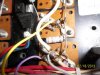
Unless you hid it real good on me, I do not see the necessary 0.33 ohm R41 on the negative side of the transistor stack. Without this, you will get NO drive to the lower half of the output bridge.
.006 Joe
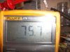
D13 left channel---.416 forward, 1.865 reverse. D13 right channel--.079 both directions.
")
When you are measuring across D13 while in circuit you are actually reading R34 in series with R35 in series with R41. Are you seeing where that is coming from?
R41 bridges from pad 6 to pad 4 on the control board. If you sketch that in on your schematic it will be easier to see this relationship.
Educated guess...I was off by 113 ohms.
Educated guess...I was off by 113 ohms.