PL7000S2

J!m

Veteran and General Yakker
Joined
Dec 24, 2019
Messages
10,668
Location
Connecticut
Tagline
BOT
#81
Yeah, without the correct tools, those things are best left untouched.

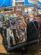
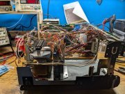
But I think trimming all the wires to exact length, and/or replacing the pins with a header connector to be able to easily demount boards in the future would be awesome. Kenwood used these too, and when I did the transport work on mine it was a nightmare to service without disconnecting anything.
 

George S.

Veteran and General Yakker
Joined
Feb 18, 2020
Messages
5,015
#84
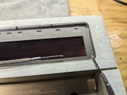
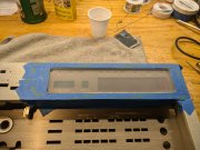
Used Goo Gone to remove stains on the face plate.
Pioneer cheaped out and used clear plastic instead of glass.
Lots of small scratches from paper towels, and 2 gouges.
Wet sanded it with 1000 grit auto body paper and polished it out with polish from a plastic headlight lense polishing kit.
Using microfiber cloths is key, no paper towels. The Rubbermaid brand microfiber cloths are awesome for cleaning flat screens and this.
Came out great. Looks excellent under magnification even from a angle.
Following the 1000 grit with 2000 would have simplified polishing. I need to get some.
 

Attachments

George S.

Veteran and General Yakker
Joined
Feb 18, 2020
Messages
5,015
#86
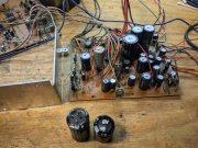
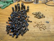
Starting the recap. All the larger caps are glued down, and, they used plenty of it.
So much spread under other components nearby.
It becomes conductive as it ages.
I'm removing the components, scraping it off with a small jewelers flat tip, then cleaning with alcohol.
The replacement Nichicon caps have a very slightly larger diameter lead than the original Elnas.
Running a small bit clearing the through holes of adhesive and debris is required.
That old glue is a PITA!
 

Attachments

George S.

Veteran and General Yakker
Joined
Feb 18, 2020
Messages
5,015
#87
Starting on the power supply. I've read these run hot, so upgrading the 85 deg C caps to 105 deg C.
The largest value Elna is a three pin, the third pin is strictly a anchor.
Replacing it with a Nichicon snap in, will need to slightly open the through holes, but nice wide traces so no problem.
Seven regulators are bolted to that heatsink.
They warped the board towards the heatsink when they bent the legs. So, they'll get removed and reinstalled on a straight board. I'll glue some rubber spacers in to keep it straight before reinstalling them.
 

Attachments

George S.

Veteran and General Yakker
Joined
Feb 18, 2020
Messages
5,015
#88
Waiting on the second round of caps order.
Got a better understanding of the boards while working on them.
Ordered some audio caps where low leakage like UKL would be the better choice, and vice versa.
Also found I need some miniature versions for a better fit, and I ordered a 63V when I needed a 6.3V.
Said it before, I seldom get it right to my satisfaction the first time!
Just made a head height adjustment tape from the sticky directions on TH.
Going to look around today for a suitable mirror to cut and try to make a mirror cassette.
 

Attachments

George S.

Veteran and General Yakker
Joined
Feb 18, 2020
Messages
5,015
#89
Starting mock up of the power supply and power distribution board.
Going to ditch the fuse holder I added and mount the IEC to the inside of the rear panel with machine screws and nuts.
That rear panel is removable for troubleshooting. This way I can remove it without disconnecting any wiring.
I'll get this section running and tested before going further.
All those new 105 deg caps sure are pretty.
 

Attachments

George S.

Veteran and General Yakker
Joined
Feb 18, 2020
Messages
5,015
#90
Brought it up on the Variac and DBT.
Looked good, so plugged her in direct.
All rails are within a volt DC of spec, no load.
There are 23 alignment trimmers in the unit that are next on the agenda to be replaced.
That's next months project.
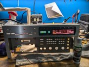
Here's a photo of the folding face plate.
A little rough like the rest of my PL gear.
Looks alright from a distance.:)
 

Attachments

George S.

Veteran and General Yakker
Joined
Feb 18, 2020
Messages
5,015
#91
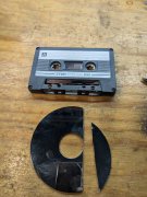
Read a post on TH where the fellow used a hard drive platter in a mirror cassette.
Works excellent.
Appears to be a first order mirror.
Platters are aluminum, so easy to cut and file.
I'll make a few more as time allows out of various other brand cassettes.
 

Attachments

George S.

Veteran and General Yakker
Joined
Feb 18, 2020
Messages
5,015
#92
Unit has 30 alignment trimmers.
Some are used as a single variable resistors, others are used as voltage dividers.
Originals are Alps sealed. Could probably have made them work, but I want the unit to hold alignment with no issues for decades.
New Bournes sealed Cermet trimmers were installed.
Went with the larger 3386 series that are 3/8" square, and fit nicely. Some of the boards reside within a RF shield, so the larger size is a plus for easier alignment.
There was one value only available in the slightly smaller 3362 series, and another in the even smaller 3329 series.
Used all original values without resorting to adding parallel resistors and affecting the trimmers linearity.
Saw no reason to go with multi-turn trimmers and complicate fitment. These single-turns are NICE and superior to the originals.
 

Attachments

George S.

Veteran and General Yakker
Joined
Feb 18, 2020
Messages
5,015
#94
Yeah man, some of the guys on TH take years rebuilding tape decks.
Luckily I'm retired and have more time to throw at it.
 

George S.

Veteran and General Yakker
Joined
Feb 18, 2020
Messages
5,015
#95
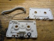
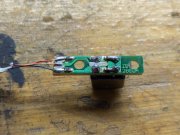
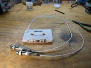
Been reading about flux loops and injecting signal directly at the head without using a tape, so I'm trying this.
I want to inject signal for frequency response sweeps through the heads with a signal generator and see the response on the QA-403 audio analyzer.
The ferrite heads on these old machines don't age well and this is a tool to help test them.
Not a tool for head alignment.
It's got a crappy too thick shell, so I'll have to sand the contact points down some, but that's O.K. as it should work for it's purpose.
That head in the shell is spring loaded and will retract as the decks head rises and contacts it.
 

Attachments

George S.

Veteran and General Yakker
Joined
Feb 18, 2020
Messages
5,015
#96
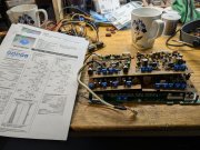
Boards are finally recapped and cleaned of all that dirt and thick coating of wave soldering flux.
Very good quality boards, not a single issue with a lifted trace or anything else.
Went ahead and replaced the ceramic .047 uF coupling caps with Panasonic ECW film, and the other smaller values with CDE silver mica. These ceramics were all used for coupling in the audio path around the Pioneer PA4001 quad opamps in the mother boards Record Amp Block, and on the Play Back Amp Block board.
 

Attachments

Last edited:

George S.

Veteran and General Yakker
Joined
Feb 18, 2020
Messages
5,015
#98
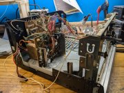
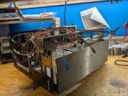
Beginning mock up.
That horizontal motherboard takes three vertical boards that plug into standard size Molex connectors.
Pins still have good plating, but many suspect cracks in the joints on several of the pins, so they got resoldered.
There is access to the foil side of the motherboard by removing the lower chassis, there's two removal access plates. Should be easy to reflow pins without major disassembly.
Now that it's starting to come together, I'm in awe at what they engineered to play a cassette!
 

Attachments

George S.

Veteran and General Yakker
Joined
Feb 18, 2020
Messages
5,015
Slow progress.
Not a fan of twisting cables, but it was the right thing to do with the header cables. Gives me room to work and I can actually see the boards. Can also now see where they begin and end.
There was a lot of point to point wiring crossing here and there, board to board, with the connections relatively inaccessible.
Pulling a single board was a PITA,
I'm unitizing it with barrier strips for the single wires that go board to board. Will be now easy to pull a board. Unplug any header cables and pull the spade terminal ends off the barrier strip.
One barrier installed for the power supply, and one for the motherboard. A additional one gets installed for the switch amp board, and perhaps a fourth if needed.
Really didn't want to install a barrier over the transformer, but no choice, just no extra room anywhere.
Made the brackets, and those aluminum standoffs will be replaced with high temp black nylon standoffs when they arrive. Should lessen chance of hum and noise.
Three vertical boards and the transport still need added.
Listening to The Myrrors-Warpainting.
 

Attachments

Last edited:
Top