PL7000S2

George S.

Veteran and General Yakker
Joined
Feb 18, 2020
Messages
4,916
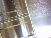
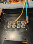
Gap erosion most likely from corrosion.
Placed a Q-Tip wetted with white vinegar over those deposits for a couple hours.
The brass underlayment is showing, the ferrite bottom of the gap is gone.
I have no idea how this will affect performance, most likely not good. We'll see. Perhaps internal adjustments can compensate.
Well. Sam and others have commented on other forums about these heads aging badly.
I'll continue with these through the build, while researching alternative heads like the Sendust and Alps Ferrite.
I'll make changes to enable easy head swapping.
 

Attachments

George S.

Veteran and General Yakker
Joined
Feb 18, 2020
Messages
4,916
Transport is working very well. The mirror cassette worked great for setting the tape guide located on the left pinch roller
I'm in the alignment procedures for setting Dolby Playback Adjustment.
Couple test points are buried deep on the motherboard, so partially disassembled it for the upteenth time and soldered in some leads.
Going to try to learn how to set Dolby Playback per the service manual, then try the supposedly more accurate way of measuring output directly at the PA4005 chip. There's four of these on the vertical Dolby board. Each channel probably has one for record and another for play.
I'll have to take it partially apart again to solder leads on the chips.
One step at a time.
Listening to Stoned Century.
 

Attachments

Bob Boyer

Veteran and General Yakker
Joined
Apr 24, 2013
Messages
2,915
Location
Chattanooga, TN
Tagline
---
Don't know that you'll ever match a 2-tire NASCAR pit stop but it sure sounds like you'll be able to disassemble and reassemble that thing in record time by the time you're done. Probably faster than I can field strip my 1911.

Great work, George!
 

George S.

Veteran and General Yakker
Joined
Feb 18, 2020
Messages
4,916
The original plastic RCA jacks are oxidized and are junk.
A clean alignment signal through them is problematic even after cleaning.
Going to make a adapter plate and install Switch Craft jacks.
Rear of the chassis comes off with zero desoldering.
Also need to file some screwdriver pry slots in the battery box cover. It's a very tight fit.
 

Attachments

George S.

Veteran and General Yakker
Joined
Feb 18, 2020
Messages
4,916
At the point where the precision of the Fluke 8920A digital meters is a hindrance.
Look at the right hand Fluke measuring the Record Dolby test point.
Knew this was point was coming so I have a Leader LMV-185A dual channel analog meter on the way.
Hopefully it's averaging function will allow a accurate adjustment.
 

Attachments

George S.

Veteran and General Yakker
Joined
Feb 18, 2020
Messages
4,916
Got the Leader analog millivoltmeter.
On the inside, looks as clean as the day it was made.
Cleaned the outside some. Got all the old stickers and tape off it.
Polished the meter window with a antistatic dryer sheet.
Both channels are dead on accurate with the HP function generator and four Fluke benchtop DMM's.
The unit works excellent, so I'll hold off on recapping it until I get the deck finished.
Weirdly, it has female PL259 sockets on the front for each channel, same as found on the rear of a Citizens Band radio transceiver.
Without a adapter, a dual banana jack will plug straight in to the PL259 and ground jack above it.
The BNC adapters that came with it aren't silver plated, and had surface oxidation, and intermittent connection.
Put them in a cup of white vinegar for a hour, they look and perform like new.
Really, a nice little unit, I'm impressed, build quality looks very good.
This one came cheap from a surplus company in Orlando FL.
Yes, the meter has two needles, one for each channel.
 

Attachments

George S.

Veteran and General Yakker
Joined
Feb 18, 2020
Messages
4,916
Playing the HPR test tapes into the QA-403 to actually see what's on them.
This is working excellent.
It's all rather confusing with the different levels and tapes, but I'm starting to get a handle on it.
I did print out English translations of the German language stickers on the tapes.
Supposedly everything I need is on the six tapes.
I just need to find it and make a note of where it's at from the tape counter.
I also now have the 4 blank tapes I'll calibrate the record portion of the deck to.
TDK D, TDK SA, Sony Duad, TDK MA-X. They're all used, I'll erase them. Should work fine.
 

Attachments

WOPL Sniffer

Veteran and General Yakker
Joined
Aug 10, 2015
Messages
11,478
Location
Minnie-Soda
Tagline
Screw it
Playing the HPR test tapes into the QA-403 to actually see what's on them.
This is working excellent.
It's all rather confusing with the different levels and tapes, but I'm starting to get a handle on it.
I did print out English translations of the German language stickers on the tapes.
Supposedly everything I need is on the six tapes.
I just need to find it and make a note of where it's at from the tape counter.
I also now have the 4 blank tapes I'll calibrate the record portion of the deck to.
TDK D, TDK SA, Sony Duad, TDK MA-X. They're all used, I'll erase them. Should work fine.

George, it's been so long since I pulled out the QA that I probably forgot how to use it.
 

George S.

Veteran and General Yakker
Joined
Feb 18, 2020
Messages
4,916
Took it apart again to check a few things, solder test leads on the Dolby chips, etc, before I start the alignment over.
Have a issue with low output at Playback EQ test points at higher frequencies, no problem with low frequencies.
Probably the heads, but could be the playback amp or a prior adjustment.
Will probably have a issue measuring at the Dolby chips because it requires the Dolby Level tape to be played. Fun, fun, fun.
 

Attachments

George S.

Veteran and General Yakker
Joined
Feb 18, 2020
Messages
4,916
The heads are junk.
Ran the 315 Hz tone at -20 dB on the QA403.
The 10 kHz tone is at -35 dB on the left channel, -38 dB on the right.
So the left channel is down 15 dB, the right is down 18 dB.
Going to do some more reading and start looking for heads.
 

George S.

Veteran and General Yakker
Joined
Feb 18, 2020
Messages
4,916
And, I soldered the Dolby Level test leads to the wrong pins. Doh!!!
I'd starve if I had to do this or anything like this for a living!.
I'll get those leads moved from pin #2 to #15 and retest.
The PL7000 service manual appears to be correct for setting Dolby Level, but I want to verify it by measuring directly at the chips.
The prior TOTL deck from Pioneer was the CT-F1250, and they say the service manual is in error.
Work around on that deck appears to be measuring at the chip while playing a Dolby Level test tape.
 
Top