You are using an out of date browser. It may not display this or other websites correctly.
You should upgrade or use an alternative browser.
You should upgrade or use an alternative browser.
PL400 Series II WOPL Quasi Control Board
- Thread starter Sunnbobb
- Start date
Pulpmillguy
Journeyman
You didn't line up all of your screw heads...


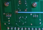
But on a serious note, is it just a reflection of something in the solder or is is a lack of solder on some of your joints, for example...? I'm hoping it is just a reflection as you can see the same in the nuts but then again some of the holes look a little "empty" and could use a little more solder.


But on a serious note, is it just a reflection of something in the solder or is is a lack of solder on some of your joints, for example...? I'm hoping it is just a reflection as you can see the same in the nuts but then again some of the holes look a little "empty" and could use a little more solder.

George is correct, nuts and internal tooth washers are on the topside of the board, Screw heads are on the bottom.Nuts should be on heatsink side. Easy fix.
Some twist, some don't. It doesn't matter.
I do not, I just keep them together with a single ty wrap near the middle of the length to keep it neat.
I do not, I just keep them together with a single ty wrap near the middle of the length to keep it neat.
Sunnbobb
Journeyman
Curious why the screw heads should be on bottom. I reversed them so I could get a socket on the nut... ps thanks for checking things out!
You should not need a socket on the nut, once you put an internal tooth lock washer on top of the TO-220 tab followed by a nut, the turning of the screwdriver will tighten the nut without the need for any sockets. Try it, you will see.Curious why the screw heads should be on bottom. I reversed them so I could get a socket on the nut... ps thanks for checking things out!
Sunnbobb
Journeyman
ok, but still wonder why it matters? Curious mind here.You should not need a socket on the nut, once you put an internal tooth lock washer on top of the TO-220 tab followed by a nut, the turning of the screwdriver will tighten the nut without the need for any sockets. Try it, you will see.
Minimize scuffing off of the solder mask around by the washer and nut. Once you scuff the green solder mask off, bare copper gets exposed right underneath. The only tinned areas of the board are those that do not have solder mask on them, around holes and such. You will note the screw head is just about the same size as the pad on the board. That is the reason, maximum longevity of your finished product over the years.ok, but still wonder why it matters? Curious mind here.
Sunnbobb
Journeyman
Gotcha. I appreciate the explanation, and something I can be aware of in other electronic endeavors. BTW, your color diagrams of hooking up the board in a former pl36 configuration are very helpful.
Sunnbobb
Journeyman
Dianne, the series II 400, is being a spoiled Princess. It has an issue. Firing it up, everything goes as planned. Then, after about 20 seconds of idling, The Output relay shuts down. If I try a restart, the Relay lights up for a brief moment and does not energize. If I wait an hour or so, I'm back to 5 seconds of idling, then after that, the brief flash on/off thing happens.
Here is what I know:
Voltage supplied 118V
Filter caps L83.5V R83.4
PL13-20 WOPL Board voltage 11L-12L 165V
Bias L/R .360 holds steady
VR L15.23 R15.38
R128 L R 11Ω
LED lights on light board are proper
DC Offset (J1-1 & J2-1 on WA Output Relay) L .7VDC R .7VDC
Relay J3-1 83VDC J3-3 59 VAC
Notes: Inputs disconnect/reconnect no difference
Replaced output and driver transistors, populated board, unpopulated board no difference.
Suggestions and berating are equally appreciated..
Last edited:
- Joined
- Jan 14, 2011
- Messages
- 75,829
- Location
- Gillette, Wyo.
- Tagline
- Halfbiass...Electron Herder and Backass Woof
What are output conditions when the DC protect relay trips?
MarkWComer
Veteran and General Yakker
- Joined
- Nov 1, 2014
- Messages
- 3,520
- Location
- Gaston, SC
- Tagline
- Victim of the record bug since age five
There were three… so I braided mine…Joe. Should the 3 wires to the bias transistor be tightly twisted, or doesn't it matter?
A question I've been meaning to ask for a long time.
Sunnbobb
Journeyman
Laatsch, DC Offset (J1-1 & J2-1 on WA Output Relay) L .7V R .7VWhat are output conditions when the DC protect relay trips?
Last edited:
volts? millivolts? microvolts?DC Offset (J1-1 & J2-1 on WA Output Relay) L .7 R .7
Sunnbobb
Journeyman
Joe, vdc, thxvolts? millivolts? microvolts?
Your offset should be around 1 millivolt (0.001V), not 700 millivolts (0.700)Joe, vdc, thx
0.7V will slowly trip the DCP
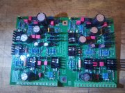
Pictures would help us help you


![20240506_041230[1].jpg 20240506_041230[1].jpg](https://forums.phxaudiotape.com/data/attachments/78/78112-36c166366a7e54a5e9a291236bb4248d.jpg?hash=NsFmNmp-VK)