Sunnbobb
Journeyman
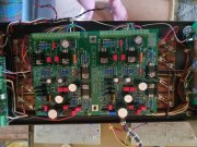
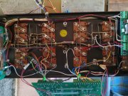
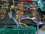
Joe, the first picture in the thread is this board.Pictures would help us help you

Joe, the first picture in the thread is this board.Pictures would help us help you
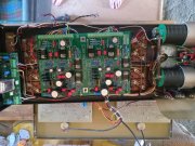
Please unlace your ty wraps going into the control board and post new pics so we can see what you have going on. I am unsure what you are doing with that white ground wire...Joe, the first picture in the thread is this board.
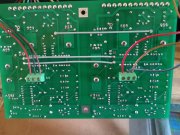
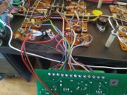
Should I be running a new wire between the copper plate and the bus, or will the inputs get their ground through 2l and 2r connections?This diagram should help, it is for a 700B but the wiring is similar. Remove that white wire going to the RIGHT channel terminal position 5. That should be OPEN. The input signals only interact with terminal block 1 and 2 positions.
Ignore the input switch shown in this diagram, the 700B has this switch but the 400 S2 does not.
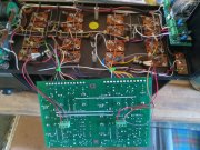
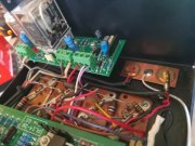
NO wire between the input jack copper plate and the bus. That creates a ground loop.Should I be running a new wire between the copper plate and the bus, or will the inputs get their ground through 2l and 2r connections?
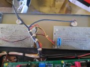
No. Not all grounds are created equal, it is important to follow the diagram or you will create a ground loop with its associated noise and hum.One last question. Can i run r2 and l2 from the copper bar, rather than all the way back to the pots, since pot post 3 (ground) already runs to the copper bar?
"Not all grounds are created equal" Boy, that sounds like you have been hanging out in my shop working on Italian Motorcycle wiring!No. Not all grounds are created equal, it is important to follow the diagram or you will create a ground loop with its associated noise and hum.
I know that this is not that intuitive but it is important.
Straight out of the Ducati service guide..."Not all grounds are created equal" Boy, that sounds like you have been hanging out in my shop working on Italian Motorcycle wiring!
Thanks for the tips boss. I really appreciate it.
Hi all. I'm following these threads closely. (Trying to make a decision on my 400 II.)
I notice that the "white wire" ground problem, identified in posts #24 & #25, is precisely what is described in the WattsAbundant relay installation procedure. I take it, that instruction is wrong.
As shown here: 400 Relay Installation Procedure
You have to scroll to the bottom to open the PDF.
![20240518_113621[1].jpg](/data/attachments/78/78306-967dffa6852172e4d98b03049ab4c7b7.jpg?hash=ln3_poUhcu)