
PL400 Series II WOPL Quasi Control Board
- Thread starter Sunnbobb
- Start date
![20240506_041230[1].jpg](/data/attachments/78/78112-36c166366a7e54a5e9a291236bb4248d.jpg)
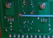
You didn't line up all of your screw heads...
But on a serious note, is it just a reflection of something in the solder or is is a lack of solder on some of your joints, for example...? I'm hoping it is just a reflection as you can see the same in the nuts but then again some of the holes look a little "empty" and could use a little more solder.
But on a serious note, is it just a reflection of something in the solder or is is a lack of solder on some of your joints, for example...? I'm hoping it is just a reflection as you can see the same in the nuts but then again some of the holes look a little "empty" and could use a little more solder.
Curious why the screw heads should be on bottom. I reversed them so I could get a socket on the nut... ps thanks for checking things out!
ok, but still wonder why it matters? Curious mind here.
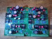
Dianne, the series II 400, is being a spoiled Princess. It has an issue. Firing it up, everything goes as planned. Then, after about 20 seconds of idling, The Output relay shuts down. If I try a restart, the Relay lights up for a brief moment and does not energize. If I wait an hour or so, I'm back to 5 seconds of idling, then after that, the brief flash on/off thing happens.
Here is what I know:
Voltage supplied 118V
Filter caps L83.5V R83.4
PL13-20 WOPL Board voltage 11L-12L 165V
Bias L/R .360 holds steady
VR L15.23 R15.38
R128 L R 11Ω
LED lights on light board are proper
DC Offset (J1-1 & J2-1 on WA Output Relay) L .7VDC R .7VDC
Relay J3-1 83VDC J3-3 59 VAC
Notes: Inputs disconnect/reconnect no difference
Replaced output and driver transistors, populated board, unpopulated board no difference.
Suggestions and berating are equally appreciated..
Last edited:
- Joined
- Jan 14, 2011
- Messages
- 74,306
- Location
- Gillette, Wyo.
- Tagline
- Halfbiass...Electron Herder and Backass Woof
- Joined
- Nov 1, 2014
- Messages
- 3,279
- Location
- Gaston, SC
- Tagline
- Victim of the record bug since age five