PL400 Build help

BrickbyBrick

New Around These Parts
Joined
Jul 30, 2022
Messages
29
#1
Hey all! First time building a WOPL and I need a helping hand.

Just wrapped up the build today and all the measurements check out except that I'm getting an insane voltage reading across the Left and Right channel bias, and by insane I mean over 50V. It only started doing this after I installed the TO-3 transistors. Before installing I was able to get the nominal 400ma reading.

I did power up the unit, unknowingly with the insane bias voltage, and sound passed, although slightly distorted in the right channel, then after about 4 minutes I saw sparks in the lower left corner and the R 5AGX fuse blew. I checked for ground at the TO-3 transistors and noticed that one leg on one transistor was bent and probably touching the chassis. Fixed the bent leg, installed a 1A AGX to play it safe this time around, and I'm still getting high bias voltages.


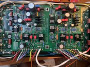
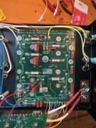
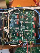
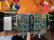
Any ideas? Please see attached photos, and thanks yall!
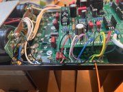
IMG_1654.JPG IMG_1653.JPG IMG_1651.JPG IMG_1650.JPG IMG_1649.JPG IMG_1648.JPG
 

BrickbyBrick

New Around These Parts
Joined
Jul 30, 2022
Messages
29
#3
Good call on the DC protect board, I'll order one.
I don't have a current limiter, after this many DIY projects I should, I usually monitor voltages with my DMM as a I slowly raise the variac.
 

BrickbyBrick

New Around These Parts
Joined
Jul 30, 2022
Messages
29
#5
Are you talking about the two black wires that are attached to the positive of the lower can cap with the buss bar?
 

gene french

Veteran and General Yakker
Joined
Mar 6, 2022
Messages
5,564
Location
guayabo de bagaces, guanacaste, costa rica....
Tagline
music...the healer of souls...
#6
Are you talking about the two black wires that are attached to the positive of the lower can cap with the buss bar?
the caps/resistors on output posts....joes backplanes have one ..the dc protect will also have one that you will need to disable....you need to remove them from the posts...then only the back planes will have one until dc protect arrives...
 

BrickbyBrick

New Around These Parts
Joined
Jul 30, 2022
Messages
29
#7
ohhhhh ok got it. Must have missed the part in the build instructions to remove the components on the output posts. Thank you!
 

BrickbyBrick

New Around These Parts
Joined
Jul 30, 2022
Messages
29
#10
That makes sense. Just looked at the schematic for the backplane and it does have that network before the output on the PCB.
 

Gepetto

Administrator
Staff member
Joined
May 15, 2011
Messages
14,042
Location
Sterling, MA
Tagline
Old 'Arn Enthusiast
#11
Hey all! First time building a WOPL and I need a helping hand.

Just wrapped up the build today and all the measurements check out except that I'm getting an insane voltage reading across the Left and Right channel bias, and by insane I mean over 50V. It only started doing this after I installed the TO-3 transistors. Before installing I was able to get the nominal 400ma reading.

I did power up the unit, unknowingly with the insane bias voltage, and sound passed, although slightly distorted in the right channel, then after about 4 minutes I saw sparks in the lower left corner and the R 5AGX fuse blew. I checked for ground at the TO-3 transistors and noticed that one leg on one transistor was bent and probably touching the chassis. Fixed the bent leg, installed a 1A AGX to play it safe this time around, and I'm still getting high bias voltages.


Any ideas? Please see attached photos, and thanks yall!
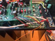
View attachment 68525 View attachment 68526 View attachment 68527 View attachment 68528 View attachment 68529 View attachment 68530
Pin 5L and Pin 5R of the back planes have an orange wire showing in them on your pictures. Those locations are supposted to be blank. You misread the instructions, the control board 5L and 5R get those wires, not the backplane.

1662167100400.png
 

Gepetto

Administrator
Staff member
Joined
May 15, 2011
Messages
14,042
Location
Sterling, MA
Tagline
Old 'Arn Enthusiast
#12
Why are all your output transistors in when you are in bring up mode? You should at most have only the bottom row in for initial bring up, that is safe mode.

Use the "brick by brick" method for assembly and bring up. One step at a time. Rushing will only cause you a lot of grief.
 

BrickbyBrick

New Around These Parts
Joined
Jul 30, 2022
Messages
29
#13
Those orange wires go to nothing. I need to snip them :)

I did install them one row at a time. Each time I checked for continuity to ground, and also used the variac to ramp up the voltage checking for anything funky, making sure I didn't blow the 1A fuses.

What I didn't check between installing the rows of transistors was the bias voltage.
 

BrickbyBrick

New Around These Parts
Joined
Jul 30, 2022
Messages
29
#14
Just checked my readings again, and the bias voltage is negative DC, and there is a negative DC voltage as well across the outputs...
 

Gepetto

Administrator
Staff member
Joined
May 15, 2011
Messages
14,042
Location
Sterling, MA
Tagline
Old 'Arn Enthusiast
#15
With all your outputs in, you cannot have insane bias voltages without having a nuclear meltdown and blow fuses. Are you sure you are measuring your bias voltage correctly.

If you had insane bias voltages with all your outputs in, the outputs would be in cross conduction and blowing fuses, output transistors and emitter resistors.

Until you get it under control, the proper thing to do is go into safe mode with only the bottom row of transistors in.
 

gene french

Veteran and General Yakker
Joined
Mar 6, 2022
Messages
5,564
Location
guayabo de bagaces, guanacaste, costa rica....
Tagline
music...the healer of souls...
#16
With all your outputs in, you cannot have insane bias voltages without having a nuclear meltdown and blow fuses. Are you sure you are measuring your bias voltage correctly.

If you had insane bias voltages with all your outputs in, the outputs would be in cross conduction and blowing fuses, output transistors and emitter resistors.

Until you get it under control, the proper thing to do is go into safe mode with only the bottom row of transistors in.
he said he blew a fuse in his initial post...
 

BrickbyBrick

New Around These Parts
Joined
Jul 30, 2022
Messages
29
#17
With all your outputs in, you cannot have insane bias voltages without having a nuclear meltdown and blow fuses. Are you sure you are measuring your bias voltage correctly.

If you had insane bias voltages with all your outputs in, the outputs would be in cross conduction and blowing fuses, output transistors and emitter resistors.

Until you get it under control, the proper thing to do is go into safe mode with only the bottom row of transistors in.
I haven't put the amp under full voltage since I blew the fuse. So I have been slowly ramping up the AC voltage with my meters connected to the bias points on the control board. When I get to about 40VAC from the variac I'm getting -50V on the bias test point.

I'll take the transistors out and give it another go! Thanks everyone for their help.
 

Gepetto

Administrator
Staff member
Joined
May 15, 2011
Messages
14,042
Location
Sterling, MA
Tagline
Old 'Arn Enthusiast
#18
I haven't put the amp under full voltage since I blew the fuse. So I have been slowly ramping up the AC voltage with my meters connected to the bias points on the control board. When I get to about 40VAC from the variac I'm getting -50V on the bias test point.

I'll take the transistors out and give it another go! Thanks everyone for their help.
When you remove them, you should check them, you may have wounded one or more.
 
Top