
- Joined
- Jul 30, 2022
- Messages
- 29
Hey all! First time building a WOPL and I need a helping hand.
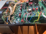
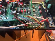
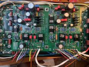
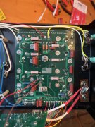
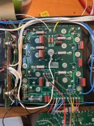
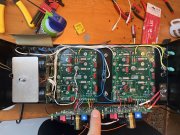
Just wrapped up the build today and all the measurements check out except that I'm getting an insane voltage reading across the Left and Right channel bias, and by insane I mean over 50V. It only started doing this after I installed the TO-3 transistors. Before installing I was able to get the nominal 400ma reading.
I did power up the unit, unknowingly with the insane bias voltage, and sound passed, although slightly distorted in the right channel, then after about 4 minutes I saw sparks in the lower left corner and the R 5AGX fuse blew. I checked for ground at the TO-3 transistors and noticed that one leg on one transistor was bent and probably touching the chassis. Fixed the bent leg, installed a 1A AGX to play it safe this time around, and I'm still getting high bias voltages.
Any ideas? Please see attached photos, and thanks yall!


")