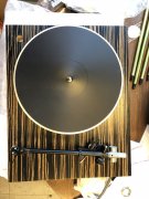
Rega Planar 3 Upgrade(?) path

J!m

Veteran and General Yakker
Joined
Dec 24, 2019
Messages
10,894
Location
Connecticut
Tagline
BOT
#62
18X18 cast aluminum jig plate is $170.00 and then there's the machining cost... Maybe I'll get up and running with the stock cables attached to the tonearm, and then plan to upgrade this later? Thinking about it...
 

NeverSatisfied

Chief Journeyman
Joined
Nov 3, 2021
Messages
916
Location
Houston Texas
Tagline
Play the Game, don’t be the Game
#63
18X18 cast aluminum jig plate is $170.00 and then there's the machining cost... Maybe I'll get up and running with the stock cables attached to the tonearm, and then plan to upgrade this later? Thinking about it...
Holy crap, did they smelt it using fairy dust? Haven’t bought aluminum stock lately but the last time I did, I bought a 2’x4’x5/8 piece of plate for less than a $100.
 

J!m

Veteran and General Yakker
Joined
Dec 24, 2019
Messages
10,894
Location
Connecticut
Tagline
BOT
#64
That's McMaster; probably a bit less direct from the mill. (but gives me an idea what it'll be from the machine shop)

If I do that, I may integrate the mini XLR connectors into the plate, rather than the add-on angle aluminum I bought. A bunch of drawing to do for that to happen...

Back to the tentacle specifications:

Original chip board Rega plinth is 6#, 0.5oz with the (sorbothane upgrade) feet attached.
New plywood plinth is 8# 2.2oz completely bare.

The aluminum plate would add (roughly) 16 pounds to the plinth, or 24+# for the plinth.

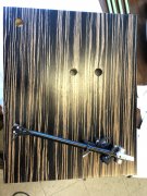
I also confirmed the new plinth HAS A FINISH ON IT! It's a satin finish, with some woodgrain visible and also some orange peel... (but not bad to use "out of the box" for 90% of the world). I'll probably block and buff it, to get rid of the orange peel and call it done. MAYBE I'll shoot it with some high-gloss clear and get a "piano" finish but I'm not sure... semi-gloss/matte is cool these days too.

Still on the fence about an IEC power connector. I guess I might as well. Maybe add a line filter in there too. Why not. Possibly both in one assembly. That's easy. Should probably add a fuse too. Why there isn't one now, I don't know, but there isn't one.

Should I rebuild the "motor control board"? A resistor and capacitor I think is the extent of it. I don't know what exactly it does so I don't know what any "upgrade" might be. Maybe it's a line filter? (I don't think so). (EDIT- after searching it is a "phasing capacitor" and resistor. I'll replace both I guess because if the cap goes bad, she won't spin. If the resistor goes bad, she won't spin, and the cap might then get fried too).
 

J!m

Veteran and General Yakker
Joined
Dec 24, 2019
Messages
10,894
Location
Connecticut
Tagline
BOT
#66
I’ll check them out but I’m going to need precisional machining in this piece anyway, so I usually let the machine shop source stock (or pull from the scrap bin).

it’s under 18x18 but it needs to be machined on the four edges and also precise location of the threaded hole for the main bearing. I’ll just have an open corner for access to the tone arm for VTA adjust (maybe a thin knurled nut large enough that it can be accessed from a slot in the side…)

A hollowed out area for motor clearance; maybe an integrated thrust bearing (in oil bath) for the motor shaft…

I need the larger vernier to accurately dimension the wood plinth so the part comes out right. The good news is I don’t have to bother with tolerance because the shop is used to making aircraft parts…
 

J!m

Veteran and General Yakker
Joined
Dec 24, 2019
Messages
10,894
Location
Connecticut
Tagline
BOT
#67
Oh, I determined the exact parts that should be on the motor board for maximum torque at reduced voltage. The lower voltage reduces vibration.

just a cap and resistor but I’m ordering a bunch so I can offer a kit to rebuild these boards. If either component fails, it either won’t run, or it will be intermittent and/or run backwards.
 

J!m

Veteran and General Yakker
Joined
Dec 24, 2019
Messages
10,894
Location
Connecticut
Tagline
BOT
#68
Okay! Now that the preamp is out of the way, time to get back to this. I’ve been working on drawings and refining things on “paper” but now I’m back on it at maximum power.

I have a decoupling scheme for the main bearing- half of it can be used on a standard deck, and I’ve already sold one! The other half is quite complicated. I will have a constrained layer sub plinth under the nice wood one. The main bearing will thread into the top plate but not contact the compressed layer or bottom plate. Tonearm will only contact the wood plinth. And the bottom nut is being made large enough to peek out the side, so you can adjust VTA without lifting the table.

The bottom most layer will have the new feet attached, and I want to attach the motor here, rather than off the wood plinth. Maybe incorporate a thrust bearing for the motor shaft too.

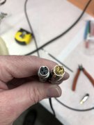
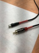
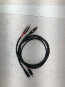
I made up the adapter cables today. I got the small diameter Mogami Negkex Quad cable and soldered it today. That somewhat sucked and I destroyed my flush cutters in rage. Pretty typical stuff. The table will be run balanced- cartridges are balanced. So, I have mini XLR outputs and the cables I made have the mate at one end and an RCA at the other.

Innthe quad two wires are “hot” (+) and the other two are “cold” (-). The cable is also shielded so it gets tricky here- the shield is connected to pin 1 (ground) at the XLR end but that shield is not connected at the RCA- hot is the tip, and cold is the sleeve. Typical single ended termination. If I get a fully balanced phono pre, I just throw in a mini XLR to standard XLR and it’s done. But, that delicate signal is shielded all the way to the phono pre at least.

Did I mention these things are small? The mini XLR is smaller than the RCA…
8C47744A-EBDC-4C81-947C-B4285BF81BE9.jpeg 8888A963-5492-4268-A8DE-3FFDDC92C7EF.jpeg 8EEB6A12-D9D3-40FB-89D4-2E0F930A75BF.jpeg DA8997C0-2340-447E-93F3-851486174EF9.jpeg

I also have standard size Neglex I’m going to make up some interconnects with for testing. I’ll probably make all new for my old system. The RCAs are Amphenol brand and pretty damn nice. Cheap too at Mouser.
 
Last edited:

J!m

Veteran and General Yakker
Joined
Dec 24, 2019
Messages
10,894
Location
Connecticut
Tagline
BOT
#70
A lot of time for little progress.

How many people do you know that do woodworking with a set of dial calipers?

IMG_4256[1].JPG
IMG_4258[1].JPG
IMG_4260[1].JPG
The Mitchell VTA adjusting nut. It raises the arm off the deck. Normally you just blow the hole open and put this on. I have a very tight slip fit so as you move the nut, it doesn't change position. It also sits flat on the top of the plinth. First try was too tight and I could barely get it out, but now it's good. Not a lot of threads in there...

I had to redesign the oversize thumbwheel for tightening the arm after adjusting height. The underside of the plinth is also counterbored because it's a bit thicker than the original. Now my thumb nut is rather massive, but combined with the top nut's tight fit, we will have good coupling to the plinth. Weather that's good or bad remains to be seen...
 

Wheel-right

Chief Journeyman
Joined
Jun 24, 2019
Messages
782
Location
SoCal
Tagline
Man, Ya shoulda been here yesterday
#71
A lot of time for little progress.

How many people do you know that do woodworking with a set of dial calipers?

View attachment 60850
View attachment 60851
View attachment 60852
The Mitchell VTA adjusting nut. It raises the arm off the deck. Normally you just blow the hole open and put this on. I have a very tight slip fit so as you move the nut, it doesn't change position. It also sits flat on the top of the plinth. First try was too tight and I could barely get it out, but now it's good. Not a lot of threads in there...

I had to redesign the oversize thumbwheel for tightening the arm after adjusting height. The underside of the plinth is also counterbored because it's a bit thicker than the original. Now my thumb nut is rather massive, but combined with the top nut's tight fit, we will have good coupling to the plinth. Weather that's good or bad remains to be seen...
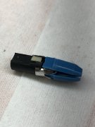
I use them all the time guitar building.
 

J!m

Veteran and General Yakker
Joined
Dec 24, 2019
Messages
10,894
Location
Connecticut
Tagline
BOT
#74
No pictures but I set the original Rega dust cover on and marked for the hinge screws. Instead of screwing direct into the wood, I’m going to use brass inserts and flanged button head screws. Much more professional and durable. It’s pretty amazing just how cheap the stock Rega is- duct tape switch mount, wood screws into chip board… for a grand you’d think they could throw us a bone…

I hope to get the constrained layer plates done tomorrow so I can get that quoted. The operator that’s making the switch bezel reached out the other day so that might be done by Friday. I gave him my idea for getting light from the LED to the level, but gave him some artistic license there… Getting that and the hinges mounted would be good progress.

I should have my Mouser order tomorrow so I’ll get the control board rebuilt. If anyone needs the cap n resistor let me know and I’ll pass them along at cost before I list them up on eBay.

the motor mount I’ve been thinking a lot about. I want to mount it to the bottom most layer (decoupled from the main bearing as well as the tone arm). I’m not going to use the Rega o-ring suspension system. They literally bend the motor mounting ears down to hook the o-ring on… I sourced an extra-resilient (but higher durometer) replacement I want to check out. Also a rather expensive square section replacement. With that, it should mount nicer and you can see if it’s twisted. That’ll be another product unless it totally sucks. If I have room, I’ll wrap the motor housing with a big, soft silicone o-ring to keep the motor can from ringing. It’s a cheap mod and I did the same on the tubes in my Counterpoint amps. Might do nothing but I don’t think it’ll hurt anything doing it.
 

J!m

Veteran and General Yakker
Joined
Dec 24, 2019
Messages
10,894
Location
Connecticut
Tagline
BOT
#75
I like the looks of those Amphenol RCA's...
They are gold plated with a turbine cut like (I think) monster cable used to do? And the body is metal, sort of a gunmetal color. Color-coded strain relief is included. I added the shrink tube to keep the shield wires from flying away. Shield is floating at the RCA end. After I was done I thought I could have run a pig tail off the shield at the RCA end as that is the same potential as the ground post for the table… but I have a ground post already so it doesn’t matter I guess.
 

NeverSatisfied

Chief Journeyman
Joined
Nov 3, 2021
Messages
916
Location
Houston Texas
Tagline
Play the Game, don’t be the Game
#76
It may end up sounding like shit, but at least it’ll look good!
I seriously doubt it will sound like shit and it already looks way better than just good. Keep up that mad scientist/artist direction and you will end up with a the high performance work of art you are envisioning.
 

J!m

Veteran and General Yakker
Joined
Dec 24, 2019
Messages
10,894
Location
Connecticut
Tagline
BOT
#78
My switch bezel is ready! I'll pick that up today.

Since I want to run the LED to illuminate the level (and indicate "power on") I need to get DC to it... or do I? I think I recall that as long as current and voltage are limited, I could run it in series with a regular diode and 4.3k dropping resistor get a 60hz "flashing" diode. That has an appeal as it could be used with a strobe, but not this time... But a 60hz flash would not be objectional in this use.

Am I imagining this, or is it true? I don't want to stuff a transformer inside this deck.

I can also hunt for 110VAC diodes, which have internal rectification. Pretty sure I've seen these but I think they may be a bit obese for the location.

Worst case I use a small bridge rectifier just for the light. Seems silly, but I have a small one I got at the local place... Maybe I should just plan to do that, with the dropping resistor and be done with it. Still fairly simple.

Help me out here smart electrical engineer types!
 

laatsch55

Administrator,
Staff member
Joined
Jan 14, 2011
Messages
74,912
Location
Gillette, Wyo.
Tagline
Halfbiass...Electron Herder and Backass Woof
#79
IIRC, they won't last as long that way, but they will work. I'll defer to Joe on this one. Hes answered that question before but I can't remember exactly what he said.
 

J!m

Veteran and General Yakker
Joined
Dec 24, 2019
Messages
10,894
Location
Connecticut
Tagline
BOT
#80
IMG_4263[1].JPG

They ended up using a slitting saw for the light to come lut so i think it's going to light up nicely!

I'll just put the rectifier in and run the LED DC. dropping resistor and done. I have room for more stuff i think...
 
Top