you can put a high voltage diode like a 1N4004 in series with your LED with an appropriate value and wattage resistor in series. It will work but it will strobe.My switch bezel is ready! I'll pick that up today.
Since I want to run the LED to illuminate the level (and indicate "power on") I need to get DC to it... or do I? I think I recall that as long as current and voltage are limited, I could run it in series with a regular diode and 4.3k dropping resistor get a 60hz "flashing" diode. That has an appeal as it could be used with a strobe, but not this time... But a 60hz flash would not be objectional in this use.
Am I imagining this, or is it true? I don't want to stuff a transformer inside this deck.
I can also hunt for 110VAC diodes, which have internal rectification. Pretty sure I've seen these but I think they may be a bit obese for the location.
Worst case I use a small bridge rectifier just for the light. Seems silly, but I have a small one I got at the local place... Maybe I should just plan to do that, with the dropping resistor and be done with it. Still fairly simple.
Help me out here smart electrical engineer types!
You are using an out of date browser. It may not display this or other websites correctly.
You should upgrade or use an alternative browser.
You should upgrade or use an alternative browser.
Rega Planar 3 Upgrade(?) path
- Thread starter J!m
- Start date
J!m
Veteran and General Yakker
Will that strobe at 60 or 120hZ? (for future reference)
Anyway, I'm going to use a bridge rectifier and dropping resistor and be done with it.
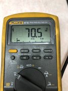
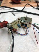
Actually, I need a 4.3k ohm at 4W minimum to drop the voltage (according to an online calculator). I have 3.9 on the motor board already (to drop voltage for the motor), so I thought I'd come after the 3.9, into the bridge and then into a 400 ohm resistor. Does that sound reasonable, or should I do it differently?
----------------------
Meanwhile, I am able to isolate the main bearing from the plinth! I have a top side o-ring (discussed earlier), which also raises the bearing off the surface of the plinth, and I have a second one, slightly counter-bored into the bottom of the wood plinth.
Under the wood plinth, is the top constrained layer plate, which will be threaded to accept the bearing.
The mechanical connection will be below the wood plinth into the top of the constrained layer only.
The motor will be in it's own motor pod, connected to the lower constrained layer, and not making contact with either the wood plinth, or the top layer of the constrained layer. I can add a "belt tension adjustment" knob on the back of the plinth that I may implement. Or, I may just have the tension "per-set" internally via spring or yet another o-ring...
J!m
Veteran and General Yakker
J!m
Veteran and General Yakker
That works out to 2.4k ohm 3 watt resistor. I think I can cram that on the board too…
J!m
Veteran and General Yakker
J!m
Veteran and General Yakker
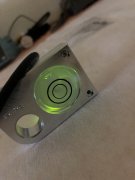
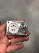
The issue is the KED projects straight out, and is at 50% output at 15 degrees off vertical. In English that means it gets dim fast as you move away from straight on.
The LED is firing straight up into a block of aluminum, with a slot in the side to deflect it into the level. An incandescent bulb would work much better but get hotter too.
I hope the new brighter one will yield more useable light. I’m afraid I’ll get a massive “hot spot” on the side of the LED but I guess we’ll see. I can always glass bead blast one side to diffuse it a bit too.
NeverSatisfied
Chief Journeyman
Hey Jim, not trying to sidetrack this thread but I want to replace the original wiring in the MA-707 arm, do you have any suggestions for replacement/upgrades?
J!m
Veteran and General Yakker
Cardas.
A company called incognito sells require kits- I’d start there and see what they have or where they can point you.
A company called incognito sells require kits- I’d start there and see what they have or where they can point you.
NeverSatisfied
Chief Journeyman
Looks like really good stuff but more than I need. I found some bulk Cardas in copper, thanks.Cardas.
A company called incognito sells require kits- I’d start there and see what they have or where they can point you.
J!m
Veteran and General Yakker
CAT5 cable…
J!m
Veteran and General Yakker
SitRep:
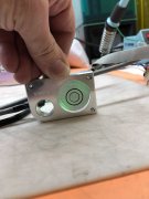
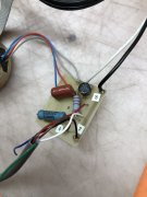
We have light you can see even with the room lights on! Not glaring due to inefficiency, but better. Board is all sorted out with added bits too.
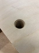
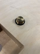
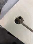
Underside counterbore is done for the bottom isolating o-ring for the spindle bearing.
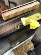
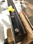
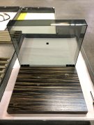

And I installed the inserts for the hinge plates. I needed to do this before installing the inserts for the switch bezel. It’ll be easier to get the position right this way.
That’s all I got done today…


We have light you can see even with the room lights on! Not glaring due to inefficiency, but better. Board is all sorted out with added bits too.


Underside counterbore is done for the bottom isolating o-ring for the spindle bearing.


And I installed the inserts for the hinge plates. I needed to do this before installing the inserts for the switch bezel. It’ll be easier to get the position right this way.
That’s all I got done today…
J!m
Veteran and General Yakker
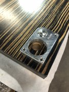
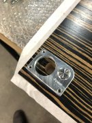
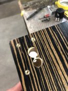
Today, the switch bezel (and a lot of drafting work).
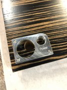
I have a bit of woodwork to do under the bezel to actually fit the switch in, but overall, not bad for hand tools.
I have the motor carrier and upper plate of the sub-plinth drawn. Just the bottom (easier) one to do next and then send out for quote.
The motor carrier will have a knob coming out the rear of the plinth which will allow the belt to be kept under constant tension- not relying on the resiliency of an o-ring wrapped around a scrap of aluminum for motor “suspension”. Vegetable tanned cow hide will isolate the top of the motor from the underside of the plinth.
The motor is in an aluminum carrier isolated by rubber and also has an added thrust bearing to keep the armature centered in the motor. The thrust ball will be another of my polymer spindle bearing balls (don’t have to order another size!), same as the main spindle. Here, I’ll probably run it dry, to reduce the mess.
NeverSatisfied
Chief Journeyman
I am sure you posted it somewhere but what polymer are you using in the bearings? Got any pics of the bearings?Today, the switch bezel (and a lot of drafting work).
View attachment 61146
I have a bit of woodwork to do under the bezel to actually fit the switch in, but overall, not bad for hand tools.
I have the motor carrier and upper plate of the sub-plinth drawn. Just the bottom (easier) one to do next and then send out for quote.
The motor carrier will have a knob coming out the rear of the plinth which will allow the belt to be kept under constant tension- not relying on the resiliency of an o-ring wrapped around a scrap of aluminum for motor “suspension”. Vegetable tanned cow hide will isolate the top of the motor from the underside of the plinth.
The motor is in an aluminum carrier isolated by rubber and also has an added thrust bearing to keep the armature centered in the motor. The thrust ball will be another of my polymer spindle bearing balls (don’t have to order another size!), same as the main spindle. Here, I’ll probably run it dry, to reduce the mess.
J!m
Veteran and General Yakker
I ain’t tellin!
But I will say they are nearly as slick as Teflon (dry) and much harder, so they don’t deflect under load. I tested a while back and put a bunch of junk (15-20 pounds) on the press to load one over the weekend, and zero deformation.
I tried a couple carbides, alumina and zirconia. Roll those, and steel, across a pane of glass and they’re all loud. The polymer is quiet. Not silent, but much lower noise.
Then you bathe it in synthetic oil…
If you would like one, I will have (3/16” diameter) available soon. I just want to do some more testing before I open the gates.
And, today, I mocked up the bearing/platter on the plinth to get the spacing of the switch bezel with the lid etc. sorted out. Dry, this thing rotates endlessly. I think we’re onto something here…
J!m
Veteran and General Yakker
The leather is just something to try.
I have a piece of nice adhesive back rubber foam around somewhere, and couldn’t locate it. But I have some leather scrap from another project and the thickness happens to be ideal.
I also know some like to use leather as a platter mat on their table, so I figured I’d give it a shot. Might be serendipitous.
I’d I locate the foam, I’ll probably switch to that.
J!m
Veteran and General Yakker
Stole some craft foam from my son today! (Not sure if I’ll use it)
A lot of set up for small progress, but it’s progress. I have the last of the drawings done, but I caught an error before I sent it out, so I have to rework that tomorrow. Sorry- engineers don’t make errors; we make revisions.
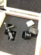
And the end of side lifter came in as well.
A lot of set up for small progress, but it’s progress. I have the last of the drawings done, but I caught an error before I sent it out, so I have to rework that tomorrow. Sorry- engineers don’t make errors; we make revisions.


And the end of side lifter came in as well.

J!m
Veteran and General Yakker
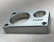
Switch bezel has been polished and brushed. Clear is on so it’s done in the morning.
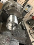
Motor Cartier is started. The motor is cradled by a large o ring at the top and a small one around the bottom bearing housing. I will also have the thrust bearing at the end of the shaft as well. 10-32 tapped hole for the drawbar to adjust belt tension.
NeverSatisfied
Chief Journeyman
I need one of those....the lathe. You've got all the toys.
J!m
Veteran and General Yakker
I have full use of it.
They were going to scrap it. I fixed it up and it’s been earning its keep making tooling.
It’s a Hardinge second operation lathe. I dream of a Hardinge Super Precision. But even this thing holds 0.001 inch and repeats. Quality.
They were going to scrap it. I fixed it up and it’s been earning its keep making tooling.
It’s a Hardinge second operation lathe. I dream of a Hardinge Super Precision. But even this thing holds 0.001 inch and repeats. Quality.
NeverSatisfied
Chief Journeyman
Nice, I played on my Dad's old Southbend when I was a kid/teenager. I plan to buy one but will wait until I retire so that I only have to move it once. Also want a 3 axis CNC router table big enough for 4x8 sheets, might do that before I retire.I have full use of it.
They were going to scrap it. I fixed it up and it’s been earning its keep making tooling.
It’s a Hardinge second operation lathe. I dream of a Hardinge Super Precision. But even this thing holds 0.001 inch and repeats. Quality.

