700/1 “Tim” WOPL driver board

laatsch55

Administrator,
Staff member
Joined
Jan 14, 2011
Messages
74,938
Location
Gillette, Wyo.
Tagline
Halfbiass...Electron Herder and Backass Woof
#81
That doesn't look stock. I've got to pop the covers and look at the one that is here. You shouldn't have 2 sets of input wires to each side of the new board.
 

laatsch55

Administrator,
Staff member
Joined
Jan 14, 2011
Messages
74,938
Location
Gillette, Wyo.
Tagline
Halfbiass...Electron Herder and Backass Woof
#82
When we redo the normal/ direct the cap is a 1uf/ 63 volt Wima poly cap. It's small enough to fit on the switch. RCA input to switch, shielded wire from switch to pot. Shielded wire from pot to board.
 

laatsch55

Administrator,
Staff member
Joined
Jan 14, 2011
Messages
74,938
Location
Gillette, Wyo.
Tagline
Halfbiass...Electron Herder and Backass Woof
#83
Drivers and heat sinks removed. Too much of a mess of thermal paste to clean in place. Gonna have to drill some holes to mount the bias transistors to the backplane and two mounting holes for the WOPL driver board anyways.
Correct.
 

AngrySailor

Veteran and General Yakker
Joined
Oct 15, 2014
Messages
3,419
Tagline
---not quite right
#84
That doesn't look stock. I've got to pop the covers and look at the one that is here. You shouldn't have 2 sets of input wires to each side of the new board.
No, I agree. That’s what looked wrong to me in the first place but the PL0171 board had two signal inputs, one from the pots, which passed through C1 on the board then the others direct from the other set of RCA jacks (through the switch). If I put the direct signal to the pot input with C1 in series, is should work as normal with only one signal from the pot to the driver board I think...
 

AngrySailor

Veteran and General Yakker
Joined
Oct 15, 2014
Messages
3,419
Tagline
---not quite right
#85
When we redo the normal/ direct the cap is a 1uf/ 63 volt Wima poly cap. It's small enough to fit on the switch. RCA input to switch, shielded wire from switch to pot. Shielded wire from pot to board.
I have a wire from both jacks to the switch, from the switch to the PL0171 and another from thebswitch to the pot then to the board. Two connections on the original board, 1 has C1 in series.
 

laatsch55

Administrator,
Staff member
Joined
Jan 14, 2011
Messages
74,938
Location
Gillette, Wyo.
Tagline
Halfbiass...Electron Herder and Backass Woof
#88
When I get home I'll post some pics of how it should be wired , you don't need 2 sets of input jacks...
 

AngrySailor

Veteran and General Yakker
Joined
Oct 15, 2014
Messages
3,419
Tagline
---not quite right
#89
That input cap will strip any DC coming in from the preamp.
I have to double check but looks like in “normal” signal goes from the “normal” pair of jacks, to The switch, to the pots, to the board through C1. In “direct” (from the direct jacks) it goes straight to the board, no pots, no cap.
 

AngrySailor

Veteran and General Yakker
Joined
Oct 15, 2014
Messages
3,419
Tagline
---not quite right
#91
That mess should be cleaned up , more low signal wiring is just an invitation for more noise.
I can tie the caps onto the switch, one set of leads to the pots then the board... just gotta watch that 220k resistor that’s there also, it’s in play in one switch position and not the other... or just eliminate the cap option...
 

laatsch55

Administrator,
Staff member
Joined
Jan 14, 2011
Messages
74,938
Location
Gillette, Wyo.
Tagline
Halfbiass...Electron Herder and Backass Woof
#92
The resistor is to squelch any voltage spike from plugging or unplugging cables. If you are running good preamps ya dont need the cap option.
 

George S.

Veteran and General Yakker
Joined
Feb 18, 2020
Messages
5,036
#95
In the meantime, you've ohmed out the 700s back wall and all components and sockets look good? My 400s both had damaged sockets from prior techs forcing those self tapping screws in with the sockets not aligned properly. Since your going full complementary on the 400(you did order the 400 back plane boards?), it may be a source of donor parts if needed. A tremendous project for the future would be rewiring that 700 full complementary with new sockets and components since no back plane boards are available for it. I really like the "Industrial" look of that amp. Have fun!
 

AngrySailor

Veteran and General Yakker
Joined
Oct 15, 2014
Messages
3,419
Tagline
---not quite right
#96
In the meantime, you've ohmed out the 700s back wall and all components and sockets look good? My 400s both had damaged sockets from prior techs forcing those self tapping screws in with the sockets not aligned properly. Since your going full complementary on the 400(you did order the 400 back plane boards?), it may be a source of donor parts if needed. A tremendous project for the future would be rewiring that 700 full complementary with new sockets and components since no back plane boards are available for it. I really like the "Industrial" look of that amp. Have fun!
Tim was a working amp with bad DC offset, the sockets look good also. Yes, maybe down the road as I get more comfortable with these jobs I’ll tackle the full comp conversion... Linda (400/1) will be a full blown, full comp WOPL. I have all the goodies for that here, backplanes included. I just wanted to cut my teeth on a driver board for Tim first.

Working in the shop rn, put some new tires on my “working” tractor, got wiring issues though, bad connection somewhere. Just jockeyed everything around in the shop to get it in out of the wind. Darn cold here today. Also just had a guy stop in wants me to fix his forklift this afternoon... joy... THEN, maybe I can get back to WOPL’n this evening.
 

Attachments

George S.

Veteran and General Yakker
Joined
Feb 18, 2020
Messages
5,036
#97
Tim was a working amp with bad DC offset, the sockets look good also. Yes, maybe down the road as I get more comfortable with these jobs I’ll tackle the full comp conversion... Linda (400/1) will be a full blown, full comp WOPL. I have all the goodies for that here, backplanes included. I just wanted to cut my teeth on a driver board for Tim first.

Working in the shop rn, put some new tires on my “working” tractor, got wiring issues though, bad connection somewhere. Just jockeyed everything around in the shop to get it in out of the wind. Darn cold here today. Also just had a guy stop in wants me to fix his forklift this afternoon... joy... THEN, maybe I can get back to WOPL’n this evening.
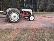
Cool!!!
 

mlucitt

Veteran and General Yakker
Joined
Jun 24, 2011
Messages
3,496
Location
Jacksonville, FL
#98
When we redo the normal/ direct the cap is a 1uf/ 63 volt Wima poly cap. It's small enough to fit on the switch. RCA input to switch, shielded wire from switch to pot. Shielded wire from pot to board.
I wonder if 0.1uF/63V would work? I have a bag full of them. The 700 schematic shows .47uF, but I believe 1uF = 40Hz.
Thoughts?
 

AngrySailor

Veteran and General Yakker
Joined
Oct 15, 2014
Messages
3,419
Tagline
---not quite right
I wonder if 0.1uF/63V would work? I have a bag full of them. The 700 schematic shows .47uF, but I believe 1uF = 40Hz.
Thoughts?
If your speakers can reproduce the frequencies, there’s LOTS to hear and FEEL below 40hz, but a single cap in series will only roll off at 6dB/oct so you’re down 6dB @ 20hz. If your speakers can’t make it, there’s no sense in amplifying it, or inducing uncontrolled cone movements.
 
Top