PL 700 II Clair Bros Rising from the Ashes

FredR

Veteran and General Yakker
Joined
Jan 26, 2014
Messages
1,529
Location
DFW
Tagline
WTF?
Thanks, Fred and Joe---and Fred again!;
It was a little further into the chassis corner. I having 'crazy' thoughts of a mini steel conduit or a steel plate between the back plane and PL14_20. I think there is space to raise the PL14_20....but then it gets closer to the power switch....
Distance matters. Inverse square law.
 

grapplesaw

Veteran and General Yakker
Joined
Aug 13, 2014
Messages
2,782
Location
Vancouver
Tagline
---
Thanks, Fred and Joe---and Fred again!;
It was a little further into the chassis corner. I having 'crazy' thoughts of a mini steel conduit or a steel plate between the back plane and PL14_20. I think there is space to raise the PL14_20....but then it gets closer to the power switch....
I use a shielded twisted pair. You can get short lengths on eBay for about $1 ft. If not in a rush sometimes half that cost. Here is what one seller claims.

This is 2 conductors twisted pair of 16 AWG shielded wires with Cross-Linked ETFE outside insulation. The wires are silver plated copper stranded each with 19 strands. The colors are white and blue. These are shielded with a silver plated copper braided shield. The shield wire is flat for greater coverage and smaller outside diameter. the outside is a Cross-Linked ETFE insulation jacket. This is very high quality mil. spec. wire. The mil. spec number is M27500A16SR2G23. This has a much smaller outside diameter than the same size with just PTFE insulation that has round braid wires instead of flat. The overall OD of this wire is aprox. 0.1550 inch (3.94mm).
 

grapplesaw

Veteran and General Yakker
Joined
Aug 13, 2014
Messages
2,782
Location
Vancouver
Tagline
---
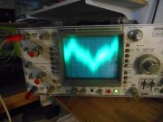
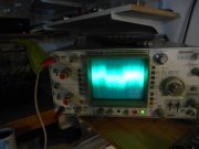
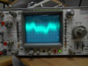
The hum/buzz in not significantly better but this will be my reference for future measurements. Scope is set to max sensitivity ( 0.5 mV / div ) on the amplifier output with an 8 ohm speaker connected. Only the scope was grounded. Input of PL14_20 has a 10 k resistor only, connected to pin 1 & 2, no other wiring.

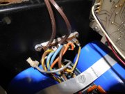
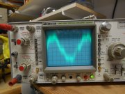
I may be on to something! ( or another goose chase ) but the AC wiring across the top of the amp; when moved closer to the control board, the hum portion of the noise increased. I believe I have routed these wires correctly but maybe they should be twisted? --or magnetically shielded? This seems to me to be a terrible design fault to have the AC line wires so close to the most sensitive components. I believe I have read that the thermal switches have been converted to DC by some. Is this part of the "Watts Abundant" DC Protection board?
Something really looks off on your scope. That curve , or lack of, is worrisome. What is the output voltage when you took that photo?
I hope you get to this curve attached
 

Attachments

Peter S

Journeyman
Joined
Jun 29, 2019
Messages
312
Location
Ontario Canada
Hi Grapple, The scope was set to 0.5 mV per division. It looks to me like 6 divisions, so about 3 mV P to P. I can hear it when my ear is six inches from the speaker. I really don't want to live with that.
 
Last edited:

BlueCrab

Journeyman
Joined
Nov 10, 2019
Messages
229
Peter, looking at the scope shot you provided, it looks to me, if I'm reading it right, the residual noise is roughly 2.5-3.0 mV P-P, at about 240 Hz. Can you confirm that?

So, if you're listening to music at 1 watt with 8 ohm speakers, my calculations have that residual noise down about 70dB from the signal. One watt @ 8 ohms gives 2.83vrms => 8v P-P. SNR = 20Log(0.003/8.0) = -68.5dB.

The constant ringing in my ears is louder than that.
 

Peter S

Journeyman
Joined
Jun 29, 2019
Messages
312
Location
Ontario Canada
Hi Blue;
I'll take your word on the calculations.....and the ringing in my ears too! But the PL700B that is currently driving the mids, is much quieter. Even my ugly Crest CA-18, which is driving the sub-woofers is dead quiet, and it has the power to rearrange the furniture. I hope to do so experimenting with the AC wires this aft.
 

Attachments

BlueCrab

Journeyman
Joined
Nov 10, 2019
Messages
229
Hi Blue;
I'll take your word on the calculations.....and the ringing in my ears too! But the PL700B that is currently driving the mids, is much quieter. Even my ugly Crest CA-18, which is driving the sub-woofers is dead quiet, and it has the power to rearrange the furniture. I hope to do so experimenting with the AC wires this aft.
But can you confirm the frequency?
 

Peter S

Journeyman
Joined
Jun 29, 2019
Messages
312
Location
Ontario Canada
Hi Blue;
Sorry, forgot to answer your main question; the fundamental frequency of the last scope trace was 60 Hz. I checked it at the time because I wanted to be sure it wasn't ripple ( 120 Hz )
 

grapplesaw

Veteran and General Yakker
Joined
Aug 13, 2014
Messages
2,782
Location
Vancouver
Tagline
---
The constant ringing in my ears is louder than that.[/QUOTE]

I know that one all to well. Mine are ringing a little loader tonight.

Talked to my Doc about this issue. He has had it for decades. He says nothing can be done at this time. It’s the membrane around the ear. It getting loader when there is inflammation in this area is increased.

On a bright note it’s the US military’s number 2 research expense for medical cures next to PTSD Lots of vets have tinnitus for all bagging and heavy shit going on.
 

grapplesaw

Veteran and General Yakker
Joined
Aug 13, 2014
Messages
2,782
Location
Vancouver
Tagline
---
This problem has peaked my interest. I will be back to the bench tomorrow for the first time since October. I want to do some tests on residual noise here and see if I can help you out. As I said in the past the it’s in there somewhere


It will be good to get back to working there again as we were tending to family all this time with weddings and then my mom coming home from the hospital to end her epic life in a safe and peaceful place. That journey has now ended this week and I feel that we accomplished that. We are all good here and Now want to finish my amazing trip thread later this month
 
Last edited:

Peter S

Journeyman
Joined
Jun 29, 2019
Messages
312
Location
Ontario Canada
So sorry about your Mom's passing. Helping your mother to be where she wanted to be, will be great solace to you and your family, now and as time passes. Thanks for taking the time for us here, during such difficulties for you.
 
Last edited:

grapplesaw

Veteran and General Yakker
Joined
Aug 13, 2014
Messages
2,782
Location
Vancouver
Tagline
---
That is interesting Peter. Some of us have been spacing the control board as far away from the back plate as possible. I put additional 1/2” standoff in there. How about taking a power cord and wiring this new power cord to the terminal strip by the power caps and in solder the old wires which will bypass the ac in the guts of the amp. you have it apart now So let’s see how that shows in the scope. Should be a piece of cake to do while it’s apart.
 

Peter S

Journeyman
Joined
Jun 29, 2019
Messages
312
Location
Ontario Canada
Hi Glen; We're thinking alike---you may want to be concerned about that! I tied that last night with the exception of leaving the internal AC wiring connected.
The control board is in it's down (installed) position for both scope traces. The amplifier is powered by the line cord tacked to the transformer terminal strip, both traces. The IEC line cord was removed but I noticed that the power switch still had an effect on the hum. Here are the results;
 

Attachments

grapplesaw

Veteran and General Yakker
Joined
Aug 13, 2014
Messages
2,782
Location
Vancouver
Tagline
---
Hi Glen; We're thinking alike---you may want to be concerned about that! I tied that last night with the exception of leaving the internal AC wiring connected.
The control board is in it's down (installed) position for both scope traces. The amplifier is powered by the line cord tacked to the transformer terminal strip, both traces. The IEC line cord was removed but I noticed that the power switch still had an effect on the hum. Here are the results;
So Peter the wires to the thermal cutoff and power switch are running through the Back plate. I would like to look at the installation of the cutoff switch and how you have this wired from the terminal strip through to the power switch and on to the input plug.

If you bypass this part of the power circuit how does it look on the scope. Move the power cord to the transformer 120 input lugs and plug cord into a power bar with a switch or use a variac to turn on and off. Please post your results.
 

Peter S

Journeyman
Joined
Jun 29, 2019
Messages
312
Location
Ontario Canada
Can I conclude that the hum is being introduced capacitively rather than inductively?----Since the power switch is only energizing the wire close to the input IC's. No current is flowing through that wiring, even with the switch on.
This could be good news because electrostatic shielding is easier than magnetic shielding. Also, the thermo switches are in the neutral side of the wiring.
Next test, just for grins; I will flip the the temporary line cord plug (hot for neutral) to see how this changes the results from above.
 

Gepetto

Administrator
Staff member
Joined
May 15, 2011
Messages
14,098
Location
Sterling, MA
Tagline
Old 'Arn Enthusiast
Hi Glen; We're thinking alike---you may want to be concerned about that! I tied that last night with the exception of leaving the internal AC wiring connected.
The control board is in it's down (installed) position for both scope traces. The amplifier is powered by the line cord tacked to the transformer terminal strip, both traces. The IEC line cord was removed but I noticed that the power switch still had an effect on the hum. Here are the results;
With the way you have it wired in the picture, isn't the power switch out of the circuit altogether?
 
Last edited:

Peter S

Journeyman
Joined
Jun 29, 2019
Messages
312
Location
Ontario Canada
Hi Glen;
I believe I have wired the amp as closely to Joe's directions as possible. The tight squeeze of the back-plane pcb's into the Clair Bros steel chassis has prevented the AC wiring from being pushed into the upper corner, so they are on top of the back-plane, closer to the input IC's. I like your idea of raising the height of the PL14_20. I am contemplating a shield under the PL14_20?

This next test was to see the result of flipping the temporary line cord polarity. The hum is very slightly higher with the power switch off. This almost makes sense to me as the wiring to the thermo switches is now 120 VAC above ground and they are not in the power switch side of the line.
 

Attachments

Top