
You are using an out of date browser. It may not display this or other websites correctly.
You should upgrade or use an alternative browser.
You should upgrade or use an alternative browser.
PL 700 II Clair Bros Rising from the Ashes
- Thread starter Peter S
- Start date
BlueCrab
Journeyman
- Joined
- Nov 10, 2019
- Messages
- 230
they are the most sensitive to RF interference (hum) because any induced RF EMF will be amplified along with the input signal.
I generally agree with the recommendations you give, but RF is defined as 20kHz to 300GHz. What's being coupled into Peter's system is AF - audio frequency - noise from the 60Hz AC line.
Peter - you can put a dead short across the audio input lines and do no harm.
grapplesaw
Veteran and General Yakker
Well have stopped waiting. I did ac supply like I always do.
Peter S
Journeyman
Hi Jim, I will try with pins 1 & 2 shorted, open, also with 1 K instead of 10 K.
IIRC, it was quite noisy with open inputs but I will check again.
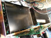
Glen, I'm also hoping to leave the AC routing stock, but I am going to also try raising the control board and possibly ferrous shield above and below. I've been called crazy, might as well confirm it.
IIRC, it was quite noisy with open inputs but I will check again.
Glen, I'm also hoping to leave the AC routing stock, but I am going to also try raising the control board and possibly ferrous shield above and below. I've been called crazy, might as well confirm it.
Peter S
Journeyman
The Shielded AC line option is still an option the I am considering. I just think it might be messy at the junction were the thermo wires come up to the lateral run at the top of the chassis?. I am going to spend a little elbow grease with some steel before I stress the AC wiring with un-soldering.
I do agree with you that it makes sense to shield the source of noise rather than the receiver, but I have a 'shoehorn' idea that is fairly simple.
I will post picks if I have any luck
I do agree with you that it makes sense to shield the source of noise rather than the receiver, but I have a 'shoehorn' idea that is fairly simple.
I will post picks if I have any luck
Always good to shield the source.The Shielded AC line option is still an option the I am considering. I just think it might be messy at the junction were the thermo wires come up to the lateral run at the top of the chassis?. I am going to spend a little elbow grease with some steel before I stress the AC wiring with un-soldering.
I do agree with you that it makes sense to shield the source of noise rather than the receiver, but I have a 'shoehorn' idea that is fairly simple.
I will post picks if I have any luck
BlueCrab
Journeyman
- Joined
- Nov 10, 2019
- Messages
- 230
You can lead a horse to water...
Peter, one last try and then I'll keep my mouth shut.
First, what's so stressing about desoldering? Piece of cake if you have some solder wick and perhaps a solder sucker. About a 15 minute job and most of that is waiting for the iron to heat up.
Twisted pair shielded is really your best option - just sayin'. Buy some of that shield twisted pair recommended earlier - great stuff. Shielded twisted pair is likely to be smaller and easier to tuck than what you currently have. You only need to ground one end of the shield (actually that's best anyhow). You can run the ground for the shield to star ground point. Here's a picture:
Glad I got that off my chest - I'm starting to feel better.
grapplesaw
Veteran and General Yakker
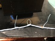
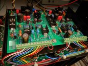
So here is my take on shielded power supply.
I got some #16 three twisted cable. It’s aircraft wire found on eBay #202655447995
I also add a thermal switch to turn fan on so use the trird wire to supply the fan circuit.
Lose wire just shows how you can pull wires through the shield.
I got some #16 three twisted cable. It’s aircraft wire found on eBay #202655447995
I also add a thermal switch to turn fan on so use the trird wire to supply the fan circuit.
Lose wire just shows how you can pull wires through the shield.
Attachments

Last edited:
grapplesaw
Veteran and General Yakker
You can lead a horse to water...
Peter, one last try and then I'll keep my mouth shut.
First, what's so stressing about desoldering? Piece of cake if you have some solder wick and perhaps a solder sucker. About a 15 minute job and most of that is waiting for the iron to heat up.
Twisted pair shielded is really your best option - just sayin'. Buy some of that shield twisted pair recommended earlier - great stuff. Shielded twisted pair is likely to be smaller and easier to tuck than what you currently have. You only need to ground one end of the shield (actually that's best anyhow). You can run the ground for the shield to star ground point. Here's a picture:
Glad I got that off my chest - I'm starting to feel better.
View attachment 39707
My question back to you is where are you taking the shield connection to. Cassis or AC input mains? I for one do not ground the chassis to AC input or service supply
BlueCrab
Journeyman
- Joined
- Nov 10, 2019
- Messages
- 230
The chassis should work fine assuming it's connect to DC ground and may work even if it's not since there is significant capacitance to earth ground. Otherwise the ground between the power supply caps. Either will provide a low impedance return to AC.
Peter S
Journeyman
Hi Jim;
Sooner or later, I will need to 'drink the water'! I really appreciate the advice and I'm glad that your input is on record in this thread. When doing it 'my way' fails, as it usually does, I will finally have to do it "The right way". I had initially considered shielding the AC wires, but Henry Ott's book says that non-ferrous shielding has no effect on electromagnetic radiation, only electrostatic.
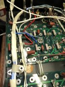
Admittedly, I believe the issue to be capacitive coupling between the AC hot wire and the control board, so copper shielding would help.
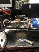
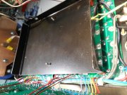
I am pursuing my crazy steel box for the control idea because of a (quite possibly hair-brained) theory that when the amp is driven harder and more current flows in Hot and Neutral AC lines, magnetic radiation will be more of an issue. Of course the hum would be harder to hear behind a large signal but still.........I could be all wet here.
Anyway, my steel box is half finished and it will work or I will toss it, and move on to your proven methods.
Thanks All, for your valuable help.....and patience.
PS; Test results to follow asap, but wife telling me to get some work done!
Sooner or later, I will need to 'drink the water'! I really appreciate the advice and I'm glad that your input is on record in this thread. When doing it 'my way' fails, as it usually does, I will finally have to do it "The right way". I had initially considered shielding the AC wires, but Henry Ott's book says that non-ferrous shielding has no effect on electromagnetic radiation, only electrostatic.
Admittedly, I believe the issue to be capacitive coupling between the AC hot wire and the control board, so copper shielding would help.
I am pursuing my crazy steel box for the control idea because of a (quite possibly hair-brained) theory that when the amp is driven harder and more current flows in Hot and Neutral AC lines, magnetic radiation will be more of an issue. Of course the hum would be harder to hear behind a large signal but still.........I could be all wet here.
Anyway, my steel box is half finished and it will work or I will toss it, and move on to your proven methods.
Thanks All, for your valuable help.....and patience.
PS; Test results to follow asap, but wife telling me to get some work done!
Attachments
- Joined
- Jan 14, 2011
- Messages
- 75,873
- Location
- Gillette, Wyo.
- Tagline
- Halfbiass...Electron Herder and Backass Woof
Hi Jim;
Sooner or later, I will need to 'drink the water'! I really appreciate the advice and I'm glad that your input is on record in this thread. When doing it 'my way' fails, as it usually does, I will finally have to do it "The right way". I had initially considered shielding the AC wires, but Henry Ott's book says that non-ferrous shielding has no effect on electromagnetic radiation, only electrostatic.
Admittedly, I believe the issue to be capacitive coupling between the AC hot wire and the control board, so copper shielding would help.
I am pursuing my crazy steel box for the control idea because of a (quite possibly hair-brained) theory that when the amp is driven harder and more current flows in Hot and Neutral AC lines, magnetic radiation will be more of an issue. Of course the hum would be harder to hear behind a large signal but still.........I could be all wet here.
Anyway, my steel box is half finished and it will work or I will toss it, and move on to your proven methods.
Thanks All, for your valuable help.....and patience.
PS; Test results to follow asap, but wife telling me to get some work done!
And....you're going to insulate that...right??
Peter S
Journeyman
I figured the steel shield would be grounded via the stand-offs. Is that not sufficient? I was also considering isolating one it from one of the mounting studs with plastic shims and a bushing, to avoid a possible loop? Thanks Lee, for any thoughts.
- Joined
- Jan 14, 2011
- Messages
- 75,873
- Location
- Gillette, Wyo.
- Tagline
- Halfbiass...Electron Herder and Backass Woof
No I was being real basic about the component leads on the back of the board touching the steel box...
Peter S
Journeyman
I will make 6-32 x 1/2" tall stand-offs that would keep the board spaced from the steel. Is that what you are referring to? May take a little more than 1/2" , my board has the screw terminals for the bias transistors on the back. I think there there is still room before I start getting close to the meter pcb's.
- Joined
- Jan 14, 2011
- Messages
- 75,873
- Location
- Gillette, Wyo.
- Tagline
- Halfbiass...Electron Herder and Backass Woof
I would line that steel box with a thin piece of insulation. I would be REAL leery of relying on space only to keep the back of the driver board from shorting out against steel box.
Peter S
Journeyman
Thanks Lee, I have some thin insulation that could serve the purpose.
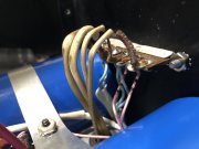
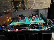
I think I'm onto something!--positive results;
I believe Jim wanted know results with input shorted rather than 10 k.
Customer at the door so no time to enter data BUT------the shield on the bottom completely fixed the issue on the right chan, 60% better on the left chan.
Planning to test with a cover on the box
Attachments
mlucitt
Veteran and General Yakker
Of course, you are technically correct. But, what we have here is 60Hz hum "radiating" through space to another wire or component. Spare us the nomenclature about frequency bands, the effect we are talking about is RF as in radiated AC signal, (transmitter and receiver) thus RF. If it were conducted as in wired AC signal or inducted as in wired DC signal, (microphone and speaker), thus AF. So, no.I generally agree with the recommendations you give, but RF is defined as 20kHz to 300GHz. What's being coupled into Peter's system is AF - audio frequency - noise from the 60Hz AC line.
Peter - you can put a dead short across the audio input lines and do no harm.