PL 700 II Clair Bros Rising from the Ashes

grapplesaw

Veteran and General Yakker
Joined
Aug 13, 2014
Messages
2,765
Location
Vancouver
Tagline
---
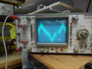
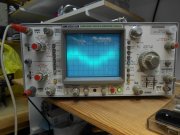
The hum/buzz in not significantly better but this will be my reference for future measurements. Scope is set to max sensitivity ( 0.5 mV / div ) on the amplifier output with an 8 ohm speaker connected. Only the scope was grounded. Input of PL14_20 has a 10 k resistor only, connected to pin 1 & 2, no other wiring.


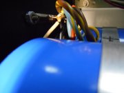
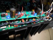
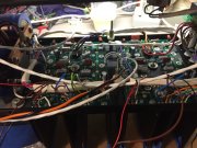
I may be on to something! ( or another goose chase ) but the AC wiring across the top of the amp; when moved closer to the control board, the hum portion of the noise increased. I believe I have routed these wires correctly but maybe they should be twisted? --or magnetically shielded? This seems to me to be a terrible design fault to have the AC line wires so close to the most sensitive components. I believe I have read that the thermal switches have been converted to DC by some. Is this part of the "Watts Abundant" DC Protection board?

Have you addressed twisting the AC wires yet?
 

Peter S

Journeyman
Joined
Jun 29, 2019
Messages
307
Location
Ontario Canada
Hi Joe;
The power switch is not switching the power to the transformer in this temporary configuration (power supplied by lamp cord soldered to term strip) but it is still connected. It is open-ended at the IEC jack but is it still energizing the internal wiring acting as one side of a capacitor?
 

Gepetto

Administrator
Staff member
Joined
May 15, 2011
Messages
13,553
Location
Sterling, MA
Tagline
Old 'Arn Enthusiast
Hi Joe;
The power switch is not switching the power to the transformer in this temporary configuration (power supplied by lamp cord soldered to term strip) but it is still connected. It is open-ended at the IEC jack but is it still energizing the internal wiring acting as one side of a capacitor?
I do not see AC wires coming into the barrier strip photo except the lamp cord wiring you attached instead of the normal wiring.
 

BlueCrab

Journeyman
Joined
Nov 10, 2019
Messages
229
Peter, if those wires going to the switch are still in the circuit, it will still create an EM field that can induce (either capacitively or inductively - it doesn't matter, probably some of both) into the input. They, the wires going to the switch, have to be totally disconnected from the AC. Even one end connected to the AC is enough to create the EM field.

QUESTION: What is the audible difference in the scope photos?
 

Peter S

Journeyman
Joined
Jun 29, 2019
Messages
307
Location
Ontario Canada
Hi Jim;
From what I gather from Henry Ott's book; if a wire is only connected at one end, current cannot flow and therefore can only radiate noise electrostatically. Twisting the radiating conductor would not completely reduce that effect. With power being supplied via IEC jack, through power switch and thermo switches, it appears that my twisting has not had any effect;
 

Attachments

Gepetto

Administrator
Staff member
Joined
May 15, 2011
Messages
13,553
Location
Sterling, MA
Tagline
Old 'Arn Enthusiast
Again, with twisted wires, tilting the PCB helped the most.
What does it look like if you route across the bottom instead of the top. And what gauge wire are you using? Appears very large.

I use 18AWG M22759/11 for the AC runs, much easier to lay up against the chassis edge.
 

Peter S

Journeyman
Joined
Jun 29, 2019
Messages
307
Location
Ontario Canada
Jim;
Regarding the audible difference" between scope traces, it seems like the larger traces is audible at 6" and I pretty much have to wear my test speaker like headphones to hear the smaller trace. (However my workshop has a little higher ambient noise than the listening room.

Joe;
I used 16 awg for the AC. My OCD seems to always kick in. Even with # 18, it wouldn't fit in the corner with the under-size Clair Bros chassis. I guess Perry was right about just using a new WO chassis..
---Wouldn't running along the bottom still be close to input wiring (inputs on terminal strip) What if 'rev H' had the inputs at the top!
 

BlueCrab

Journeyman
Joined
Nov 10, 2019
Messages
229
From what I gather from Henry Ott's book; if a wire is only connected at one end, current cannot flow and therefore can only radiate noise electrostatically.
So? Agree that no current is running through that particular wire, but it can, and does inject noise in your system electromagnetically. That AC field in that wire is expanding and collapsing at 60Hz. Any wire nearby will have a voltage induced in it.
 

grapplesaw

Veteran and General Yakker
Joined
Aug 13, 2014
Messages
2,765
Location
Vancouver
Tagline
---
Jim;
Regarding the audible difference" between scope traces, it seems like the larger traces is audible at 6" and I pretty much have to wear my test speaker like headphones to hear the smaller trace. (However my workshop has a little higher ambient noise than the listening room.

Joe;
I used 16 awg for the AC. My OCD seems to always kick in. Even with # 18, it wouldn't fit in the corner with the under-size Clair Bros chassis. I guess Perry was right about just using a new WO chassis..
---Wouldn't running along the bottom still be close to input wiring (inputs on terminal strip) What if 'rev H' had the inputs at the top!
Peter I like to elevate the AC wires away from the back plate and below the control board.
here are some shots. This is in one of Joe’s cases and I used #14 for the AC wires.
 

Attachments

Peter S

Journeyman
Joined
Jun 29, 2019
Messages
307
Location
Ontario Canada
Good Morning Folks;
Hi Blue, yes, noise is noise. I was thinking that magnetically induced noise would be more of a problem because non ferrous shielding is not effective. Regardless, I have a routing problem.
Glen, I will be raising the control board, thanks for the pictures. BTW, love that copper busbar! I thought mine was over the top.
Any thoughts about an aluminum or steel shield under or around the control board?
 

mlucitt

Veteran and General Yakker
Joined
Jun 24, 2011
Messages
3,373
Location
Jacksonville, FL
The Control Board does not require shielding. Most of the current flow on the Control Board is DC, with very low level AC current flow. DC only generates external electromotive force (EMF) if the wires move, as in a generator. Because none of the traces on the Control Board move, almost no DC EMF is electrostatically or electromagnetically generated by capacitive or induced coupling into active signal wires that would result in hum. (thanks BlueCrab)
The primary source of radio frequency (RF) EMF is the 60Hz AC power wires in the amplifier. The solutions are to: 1) create separation between the power (radiator) wires and the signal (receiver) wires and, 2) shielding either the radiator or the receiver wires. This is why we shield the input wires going to the Control Board; they are the most sensitive to RF interference (hum) because any induced RF EMF will be amplified along with the input signal. We also try to cross any AC wires at right angles to reduce any capacitive coupling that might occur if the wires run parallel to each other, even for a short run.
Joe recommends tucking the smaller 18AWG M22759/11 60Hz AC wires along the edge of the bottom of the amplifier. This Mil-Spec wire is capable of handling 15 Amps at 80 deg (C) and tucking the wire into the 90 degree channel will theoretically reduce the EMF by 50%. (ref: https://www.coonerwire.com/amp-chart/ )

Thoughts?
 

grapplesaw

Veteran and General Yakker
Joined
Aug 13, 2014
Messages
2,765
Location
Vancouver
Tagline
---
I will ask the question , possibly all ready answered, are the input wires from the RCA plugs shielded? And if so is only one end of that shield grounded and to where is that ground connection.
 

Peter S

Journeyman
Joined
Jun 29, 2019
Messages
307
Location
Ontario Canada
For these tests the input wiring is disconnected and pins 1 & 2 on each channel have a 10 k resistor across them.

BTW; is this a reasonable value? I would hope that the output impedance of my source ( miniDSP ) would be lower but I could not find the value in the spec info.
 

Gepetto

Administrator
Staff member
Joined
May 15, 2011
Messages
13,553
Location
Sterling, MA
Tagline
Old 'Arn Enthusiast
Peter it is easy to see if it responds positively or negatively to lower resistor values. The AC output impedance of most SS preamps is much lower than 10K
 
Top