PL 700 II Clair Bros Rising from the Ashes

Gepetto

Administrator
Staff member
Joined
May 15, 2011
Messages
13,907
Location
Sterling, MA
Tagline
Old 'Arn Enthusiast
Thanks J!m;
I may need a bigger oxy-acetylene torch to finish this amp project.

Hi Joe;
The angle was not electrically connected to the chassis. I just connected it and found no difference in hum/buzz. I actually first noticed the problem with the amp closed up in the listening room. Background noise in the workshop masked the issue initially.
Hard to recollect the status of the amp when you did your listening room test, too many things flying around and no results summary for each.

Could it be that you had the center tap of the transformer tied to the 3rd wire of the IEC at that time?
 

Peter S

Journeyman
Joined
Jun 29, 2019
Messages
312
Location
Ontario Canada
Yes Joe, the IEC ground was tied to centre-tap buss at the time, thanks for following so closely! I did try the amp in the listening room with an IEC cord having the ground pin clipped. Still had a low level hum/buzz.
 

Peter S

Journeyman
Joined
Jun 29, 2019
Messages
312
Location
Ontario Canada
Hi Grapple; Just found it, looks extremely informative! 400 pages---should keep me off Joe's back for a month!

Friends on another forum suggested this leakage test:
"short the main primary wires together, short the secondary wires together, and then apply mains across the two with a 1 k resistor in series and connect your meter across the 1k resistor. Use your variac to gradually turn up the voltage"

Results; 104 mVAC on this amp (a leakage current of 104 uA)

My second PL700 II, (project not yet started) measured 105 mVAC......And this amp has no visible corrosion!
 

Gepetto

Administrator
Staff member
Joined
May 15, 2011
Messages
13,907
Location
Sterling, MA
Tagline
Old 'Arn Enthusiast
Hi Grapple; Just found it, looks extremely informative! 400 pages---should keep me off Joe's back for a month!

Friends on another forum suggested this leakage test:
"short the main primary wires together, short the secondary wires together, and then apply mains across the two with a 1 k resistor in series and connect your meter across the 1k resistor. Use your variac to gradually turn up the voltage"

Results; 104 mVAC on this amp (a leakage current of 104 uA)

My second PL700 II, (project not yet started) measured 105 mVAC......And this amp has no visible corrosion!
The practical reality is that on US (and Canadian) mains, you will experience only half that leakage due to winding coupling factors. That is because one end of the primary is connected to neutral and the other to the line. This effectively splits the primary side voltage seen on that coupling capacitor in half which is consistent with the in system currents you are experiencing.
 

Peter S

Journeyman
Joined
Jun 29, 2019
Messages
312
Location
Ontario Canada
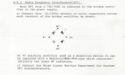
Going back to address a few issues that are not quite right. The Phase Linear service bulletin called for .01 ufd 1000 V ceramic or mylar caps as snubbers on the bridge. I used what I had ( 0.33 ufd) Would these be better? The voltage rating is 400 V but I can't see how this is not suitable for this application.
 

Attachments

grapplesaw

Veteran and General Yakker
Joined
Aug 13, 2014
Messages
2,775
Location
Vancouver
Tagline
---
Going back to address a few issues that are not quite right. The Phase Linear service bulletin called for .01 ufd 1000 V ceramic or mylar caps as snubbers on the bridge. I used what I had ( 0.33 ufd) Would these be better? The voltage rating is 400 V but I can't see how this is not suitable for this application.
The higher capacitance .33uf requires a longer time to charge and therefore may not work well in this application. The .01 if is proven to work well. i found this out the hard way when adding to large caps to the rails of opa2134 opamps in the past. Sometime smaller is better In electronics, just to be clear where smaller is better.
 

Peter S

Journeyman
Joined
Jun 29, 2019
Messages
312
Location
Ontario Canada
Thanks again, Grapplesaw, for the book recommendation; "Henry Ott - Noise Reduction Techniques in Electronic Systems [2nd Edition, 1988 Wiley & Sons". Much of it is beyond me but every aspect seems to be summarized in down-to-earth terms(no pun intended).
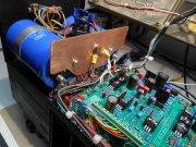
Here is my new ground bus. It might provide some electric (not magnetic) shielding from the power supply section and reduce any possible voltage drop issues between the caps and centre connection. The connection is a copper 1/4-20 bolt with copper lugs which will allow simpler trouble-shooting rather than wrestling with that monster solder joint. My snubber capacitors have been changed to the proper 0.01 ufd size.
 

Attachments

Peter S

Journeyman
Joined
Jun 29, 2019
Messages
312
Location
Ontario Canada
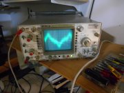
The hum/buzz in not significantly better but this will be my reference for future measurements. Scope is set to max sensitivity ( 0.5 mV / div ) on the amplifier output with an 8 ohm speaker connected. Only the scope was grounded. Input of PL14_20 has a 10 k resistor only, connected to pin 1 & 2, no other wiring.

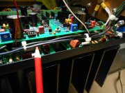
I may be on to something! ( or another goose chase ) but the AC wiring across the top of the amp; when moved closer to the control board, the hum portion of the noise increased. I believe I have routed these wires correctly but maybe they should be twisted? --or magnetically shielded? This seems to me to be a terrible design fault to have the AC line wires so close to the most sensitive components. I believe I have read that the thermal switches have been converted to DC by some. Is this part of the "Watts Abundant" DC Protection board?
 

Attachments

J!m

Veteran and General Yakker
Joined
Dec 24, 2019
Messages
10,646
Location
Connecticut
Tagline
BOT
I don't know much but I would think twisting those A/C lines might help.

Someone smarter than me might have a better solution; perhaps routing as far as possible from the sensitive stuff. But either way, I think I'd twist them, since it's free.
 

BlueCrab

Journeyman
Joined
Nov 10, 2019
Messages
229
Agree. Twisting them should help and shielded twisted pair perhaps even more (with the shield grounded at one end only). Those run close to the input op amps on the PL14/20 board, so that may be where the induced hum/noise is coming from.

Perhaps you can try bypassing the thermal switch altogether (just temporarily and just for the test) to keep the AC away from this area.
 

FredR

Veteran and General Yakker
Joined
Jan 26, 2014
Messages
1,527
Location
DFW
Tagline
WTF?
Joe recommends twisting all AC wiring in order to reduce the field generated. Also run AC as far away as possible from DC / low voltage. AC along the top of a 700 chassis and DC along the bottom.
 

Peter S

Journeyman
Joined
Jun 29, 2019
Messages
312
Location
Ontario Canada
Thanks guys, that will be my next quick test; I will clip a line cord directly to the transformer, if there is still hum from those AC wires, I guess that would be from an electrostatic effect rather than magnetic.
I will also try to flip the PL14_20 up, away from the thermo switches.
 

FredR

Veteran and General Yakker
Joined
Jan 26, 2014
Messages
1,527
Location
DFW
Tagline
WTF?
Hi Fred, my AC is routed along the top but that is where the op/amp IC is located.
Not much to be done about that. Better than at the bottom where all the control board wiring is. I twist and then tuck as far down as I can toward the heatsinks. Doglegs to the thermal switches. Maybe Joe could chime in as to whether shielded cable would help.
 

Gepetto

Administrator
Staff member
Joined
May 15, 2011
Messages
13,907
Location
Sterling, MA
Tagline
Old 'Arn Enthusiast
The hum/buzz in not significantly better but this will be my reference for future measurements. Scope is set to max sensitivity ( 0.5 mV / div ) on the amplifier output with an 8 ohm speaker connected. Only the scope was grounded. Input of PL14_20 has a 10 k resistor only, connected to pin 1 & 2, no other wiring.

I may be on to something! ( or another goose chase ) but the AC wiring across the top of the amp; when moved closer to the control board, the hum portion of the noise increased. I believe I have routed these wires correctly but maybe they should be twisted? --or magnetically shielded? This seems to me to be a terrible design fault to have the AC line wires so close to the most sensitive components. I believe I have read that the thermal switches have been converted to DC by some. Is this part of the "Watts Abundant" DC Protection board?
The AC wiring should be tucked into the chassis right angle bend just above the backplane boards. Perhaps you brought it out just to show the routing in the photo.
 

Peter S

Journeyman
Joined
Jun 29, 2019
Messages
312
Location
Ontario Canada
Thanks, Fred and Joe---and Fred again!;
It was a little further into the chassis corner. I having 'crazy' thoughts of a mini steel conduit or a steel plate between the back plane and PL14_20. I think there is space to raise the PL14_20....but then it gets closer to the power switch....
 

J!m

Veteran and General Yakker
Joined
Dec 24, 2019
Messages
10,646
Location
Connecticut
Tagline
BOT
In my last house I was toying with the idea of running the main A/C line for the stereo system across the house inside a piece of ridgid conduit to keep that one a/c line as clean as I could for the stereo.

Power was across the house from the panel there. In this house the outlet is directly above the panel!
 
Top