700B blew one Right channel 5A supply fuse

laatsch55

Administrator,
Staff member
Joined
Jan 14, 2011
Messages
74,987
Location
Gillette, Wyo.
Tagline
Halfbiass...Electron Herder and Backass Woof
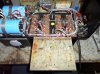
I'm sorry Gary, we're confusing you. On the factory set up that #16 silid wire does tie everything together to ground, in a WO conversion , the ground plate is isolated from chassis ground and grounded through the driver board. If you cut the #16 bare wire yours will also be this way. Those 220K resistors keep those small caps on the direct/normal coupling switch discharged when nothing is plugged in. The factory driver board is also grounded to the chassis by rhe small white wire coming off the board, and the rca's are grounded to the board by their ground wire in the shielded pair.
The White Oak boards treat this whole grounding scheme a bit different as its ground wire goes to star ground insted of the 3 terminal strip on the right. Cut the #16 bare wire between the D/N switch and copper plare, cut the #16 bare wire between the D/N switch and the speaker ground posts, that should do it...
 

62vauxhall

Veteran and General Yakker
Joined
May 14, 2014
Messages
2,324
Location
Southwest Kootenays BC
Tagline
No such things as bad days, just bad moments
No worries. Like I said earlier, I confuse easily.

Did what you said, snipped off both those connections, wired and installed the the RCA jacks and hooked up the new co-axial leads with no shorts (yet).

When removing the ground wire to the copper plate, I saw two resistors from it (chassis ground) to the Normal/Direct switch. Hard to tell colour, but they are either 220 Ohm or 330 Ohm. They do not appear on the revised schematic from the WOPL Archives. Should I remove them or leave them in place?

I have some 1/2 Watt - 220 Ohm resistors. Should I connect two between the input pins and copper plate?

Is that Normal/Direct switch missing from the factory schematic? If those resistors I found are R52 on the diagram, there's no switch there.
 

laatsch55

Administrator,
Staff member
Joined
Jan 14, 2011
Messages
74,987
Location
Gillette, Wyo.
Tagline
Halfbiass...Electron Herder and Backass Woof
Those are 220----K---ohm resistors. Leave them like they are. On the schematic they are right after the input jacks with a sliding symbol....Until such time as you want to White Oak that amp let's leave things on that end as they are now, you have a factory board , so let's treat it like one, (well, as best we can)....
 

62vauxhall

Veteran and General Yakker
Joined
May 14, 2014
Messages
2,324
Location
Southwest Kootenays BC
Tagline
No such things as bad days, just bad moments
Once again, thanks and as matter of fact, a lead was broken from one of those 220 K ohm resistors but had some on hand so replaced it.

Next step is wiring up the new board?

I just now see that the connection pads do not have through the board holes. That is gonna be loads of fun.
 

laatsch55

Administrator,
Staff member
Joined
Jan 14, 2011
Messages
74,987
Location
Gillette, Wyo.
Tagline
Halfbiass...Electron Herder and Backass Woof
Gary, I just got a 700B in here with the PL20 board in it. Let's plan on tonight after I get caught up with paperwork, I'll open this one up and I'll go wire by wire where it goes from where. In the meantime, check each wire where it comes off the backplane for broken strands, I'd be surprised if you had none with broke strands. Get those replaced, then will get that board soldered up tonight....how's that sound?
 

laatsch55

Administrator,
Staff member
Joined
Jan 14, 2011
Messages
74,987
Location
Gillette, Wyo.
Tagline
Halfbiass...Electron Herder and Backass Woof
If you have a small handheld pin vise and the appropriate size bit you can make some holes. Look that board over closely, every hole that has those new big caps has been drilled. It can be done, but you have to start on the foil side and BE VERY GENTLE....I really don't have a system for holding those wires in place to actually use both hands to solder with, unless you have a 3rd hand type positioning vise.....
 

62vauxhall

Veteran and General Yakker
Joined
May 14, 2014
Messages
2,324
Location
Southwest Kootenays BC
Tagline
No such things as bad days, just bad moments
Fine by me. The wires all look good, the solder connections to the back are intact and no loose strands. All but one wire which broke off at the board end some time ago, has the tinned end to attach to the board.

My concern at the moment, is the co-axial shields. There is a lot more material on these new leads than with the factory ones. Guess I can solder a short length of wire to the board then solder the other end to the co-ax and use some heat shrink.

I can run errands this afternoon. Any idea what time I should return to this forum?
 

Gepetto

Administrator
Staff member
Joined
May 15, 2011
Messages
14,091
Location
Sterling, MA
Tagline
Old 'Arn Enthusiast
Thanks. I read through the posts and looked at the schematics oldest to newest and unless I am grossly mistaken, the (as it's so descriptively called) floating ground plate should not have a ground wire soldered to it.


There most certainly is in mine and I might add, an outrageous amount of solder was used to make the connection. It is therefore not a floating ground plate in this case.
View attachment 14829


The other end goes to a chassis grounding tab at the Normal/Direct switch.
View attachment 14830


But it is isolated mechanically from the chassis by these spacers.
View attachment 14827


If I clipped that wire off, it would certainly isolate the input jacks. Should I do that?

If that ground shouldn't be there yet it is, was it added after manufacture?


Also there are no 220 Ohm resistors from input pin to ground. Does that apply strictly to WOPL conversions or all 700B's?

If I examined your schematics more closely, I may find other differences.
All 700Bs benefit from it. Unfortunately PL did not do a great job on understanding the ground scheme in the amp. I am sure they had their reasons.
 

laatsch55

Administrator,
Staff member
Joined
Jan 14, 2011
Messages
74,987
Location
Gillette, Wyo.
Tagline
Halfbiass...Electron Herder and Backass Woof
Ok Gary, got Stephen's 700B that used to belong to Bob Carver until he lost it in a bet to Stephen Evans....opened up and ready to go. To make things clear, with the front of the amp facing you the bottom tow , left to roght drivewrs are,

Q11, Q12..........Right side..Q11, Q12

\ The first row of outputs
Q13, Q14........Right side...Q13,Q14

Positive drive left channel far left, negative drive next right,

Positive drive tight channel next, negative drive right channel far right....
 

Attachments

laatsch55

Administrator,
Staff member
Joined
Jan 14, 2011
Messages
74,987
Location
Gillette, Wyo.
Tagline
Halfbiass...Electron Herder and Backass Woof
I will start on the extreme lefyt of the bottom of the board....

Hole #1, black...Unfused B- feed....Minus terminal on the bottom big power supply cap.

When you have successfully soldered that connection post back...
 

laatsch55

Administrator,
Staff member
Joined
Jan 14, 2011
Messages
74,987
Location
Gillette, Wyo.
Tagline
Halfbiass...Electron Herder and Backass Woof
Ok, I'm goig to be refreshing the page every few seconds so we can go a little faster here. If you click on the "new posts" on the header every minute or so we'll move right along. Please don't be offended of some of my questions seem a little too obvious, don't want to take chances...


Ok, Hole # 2, White with a green stripe, goes to the base bus bar between the driver and output, positive drive left channel
 

62vauxhall

Veteran and General Yakker
Joined
May 14, 2014
Messages
2,324
Location
Southwest Kootenays BC
Tagline
No such things as bad days, just bad moments
Ok, I'm goig to be refreshing the page every few seconds so we can go a little faster here. If you click on the "new posts" on the header every minute or so we'll move right along. Please don't be offended of some of my questions seem a little too obvious, don't want to take chances...


Ok, Hole # 2, White with a green stripe, goes to the base bus bar between the driver and output, positive drive left channel
Done.
 
Top