wattsabundant
Chief Journeyman
Better yet, read the P/L service manual on how to test outputs. Keep in mind this was written before digital voltmeters with the diode range were introduced

Go back to post #65 and #66suggestions steve???


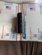
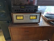
congratulations!!!!Today I felt like a kid on Xmas day when I got home from work and found this waiting for me!
So excited I will somehow get over the postal service here being so shit.
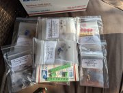
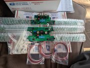
The packaging of the gear for shipping was faultless as is the the individual component packaging. It seems Joe has thought of all the little things that ensure customer satisfaction and confidence, something I believe is rarely found in the current business sector.
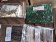
I starting it off tomorrow after work by replacing the light board and power caps in my original 4 finner first. I am in the process of finalising my next order from Joe so will do the BR upgrade when I get the snubber kits with that order.
The question I want to ask is what is the recommendation on the best board to start constructing for a first timer like me?
Anyway here's the pics you all keep telling me you want to see.
I envy you- these projects are a lot of fun, and the sense of accomplishment when it’s finished can’t be beat!Today I felt like a kid on Xmas day when I got home from work and found this waiting for me!
So excited I will somehow get over the postal service here being so shit.
The packaging of the gear for shipping was faultless as is the the individual component packaging. It seems Joe has thought of all the little things that ensure customer satisfaction and confidence, something I believe is rarely found in the current business sector.
I starting it off tomorrow after work by replacing the light board and power caps in my original 4 finner first. I am in the process of finalising my next order from Joe so will do the BR upgrade when I get the snubber kits with that order.
The question I want to ask is what is the recommendation on the best board to start constructing for a first timer like me?
Anyway here's the pics you all keep telling me you want to see.
(I wasn’t gonna shamelessly plug myself…)And don't overlook Marks WOPL building videos on YouTube!!!!
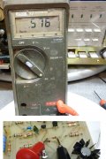
those meters are pretty tough i am told...they can be damaged if high output and 10 watt meter setting...Thanks gene
Just had a look at one of the boards I haven't installed yet and saw the moveable jumpers!
Dumbass move by me yet a cheap lesson in the checking and cross checking needed when populating the control board and back planes.
Anyway the switch is not needed for me as I will rarely change it so the jumpers are perfect.
Most of the time the handbrakes are here(wife and kids) so volume is low. I figured now that I can actually see the meters I might as well see them move.
I guess when it does get cranked up the meters won't be harmed if they are constantly in the red?
I don’t think that’s normal…I just unplugged it to open it up and approximately 2-3 seconds after power off the meters jumped close to the 0(red zone) then very slowly went back to resting state.
Is this a normal thing because I don't remember seeing it before?