WOPL 400 Down Under

MusicSteve

Journeyman
Joined
Mar 6, 2022
Messages
359
Location
Minnesota
Tagline
Always Thinking Outside The Box.
#61
Ok just had another look at it, for info left channel is putting out DC.

Left channel
Q8 marked 2n1304
Q9 marked 2n1305

Right channel
Q8 marked 2n1308
Q9 marked 2n1307

Does this sound right?

Also there is a resistor in parallel to d8 on both channels
Left is 3.8k and right is 1.5k.
Right channel also has no heatsinks on q7 and q10.
Everything else looks factory or has been done by someone proficient with an iron.
Board is a 14b.
No should be the same, I would questline it (but it might work) and one is NPN and the other is PNP
Also there is a resistor in parallel to d8 on both channels
Left is 3.8k and right is 1.5k.

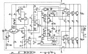
No, this is part of the bias (I would check the each diode D6,D7,D8 and all together note- if I have the correct drawing (never had this board,,,,, Gene do you have a schematic of this board, mine is not to clear)
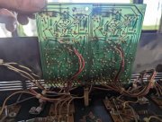
Do you have a Pic of the back of the control Board?
if you can , Try to find out wear the heat is generating at? (Infrared Laser Thermometer)
Good luck
 

gene french

Veteran and General Yakker
Joined
Mar 6, 2022
Messages
5,225
Location
guayabo de bagaces, guanacaste, costa rica....
Tagline
music...the healer of souls...
#63
Also would I need to replace q8,q9 on both channels?
before you just wholesale change a bunch of parts....it would be more beneficial to find out what/why took them out in the first place...
or you will just be in a vicious cycle...ask me how i know that too??
I got a repair kit for my board ... the 400c...it predates the pl14 boards....was not expensive....had most transistors...but not bias transistors...
your mileage may vary....
and a cap kit which was not expensive either....the caps will need changing regardless if you are not going to wopl....those caps are nearly 50 years old...and in desperate need of changing...
the rest i think would be better change when necessary...
imho...
good luck...i find this very rewarding...
 

Gepetto

Administrator
Staff member
Joined
May 15, 2011
Messages
13,557
Location
Sterling, MA
Tagline
Old 'Arn Enthusiast
#64
before you just wholesale change a bunch of parts....it would be more beneficial to find out what/why took them out in the first place...
or you will just be in a vicious cycle...ask me how i know that too??
I got a repair kit for my board ... the 400c...it predates the pl14 boards....was not expensive....had most transistors...but not bias transistors...
your mileage may vary....
and a cap kit which was not expensive either....the caps will need changing regardless if you are not going to wopl....those caps are nearly 50 years old...and in desperate need of changing...
the rest i think would be better change when necessary...
imho...
good luck...i find this very rewarding...
HUH?? :)
 

MusicSteve

Journeyman
Joined
Mar 6, 2022
Messages
359
Location
Minnesota
Tagline
Always Thinking Outside The Box.
#65
I would definably take a tooth brush and Isopropyl and clean the board and only Scrap the board not the solder joints or traces w a small screwdriver to remove the old flux (bottom left looks bad might have open trace on the board) and check all the foils that go to the next component (Buzz out) after cleaning also check for cold solder joints I see some, Then take another pic
 
Last edited:

MusicSteve

Journeyman
Joined
Mar 6, 2022
Messages
359
Location
Minnesota
Tagline
Always Thinking Outside The Box.
#66
Than I would visually check your board to Gene Board
The resistor on D8 might be causing heat to your Output Transistors since its part of the Bias circuit?
Joe why would some one do this and what would it do or cause? could check diode's and remove resistor? (take a diode from your other board if needed)
 

Gepetto

Administrator
Staff member
Joined
May 15, 2011
Messages
13,557
Location
Sterling, MA
Tagline
Old 'Arn Enthusiast
#68
Than I would visually check your board to Gene Board
The resistor on D8 might be causing heat to your Output Transistors since its part of the Bias circuit?
Joe why would some one do this and what would it do or cause? could check diode's and remove resistor? (take a diode from your other board if needed)
I guess I will have to focus on this thread to answer that Steve...maybe tomorrow.
 
Joined
May 24, 2021
Messages
61
#69
I have just removed the balanced input junk there is 5 wires going to the control board. Three of them are earths that went to the left input with a jumper cable connecting to the right negative. There is also a bridging going to the right channel ground only.
When I reconnect to RCA's how should I ground it?
 

gene french

Veteran and General Yakker
Joined
Mar 6, 2022
Messages
5,225
Location
guayabo de bagaces, guanacaste, costa rica....
Tagline
music...the healer of souls...
#70
I have just removed the balanced input junk there is 5 wires going to the control board. Three of them are earths that went to the left input with a jumper cable connecting to the right negative. There is also a bridging going to the right channel ground only.
When I reconnect to RCA's how should I ground it?
they are isolated from the chassis...
my new rca jacks came with insulators...
 
Joined
May 24, 2021
Messages
61
#71
Sorry I didn't ask the right question.
I get the earth for each channel but don't understand the third earth. Especially when the three earth's coming from the board went to the one spot
 
Joined
May 24, 2021
Messages
61
#73
Ok, diode check done.
First number forward biasing second reverse
Left channel
1 598, 611
2 611, 597
3 621, ol
4 604, 1.874
5 598, 1.8
6 as above
7 same
8 587, 1.535
9 600, ol
10 621, ol
11 600, 1.9
12 as above
13 0.071, 0.071
14 450, ol
15 as above

Right channel had pretty close to same figures except for
D8 was 563, 965
I assume that is due to the parallel resistor
D10 is non existent

Gonna pull the outputs from the bad channel now.
 
Joined
May 24, 2021
Messages
61
#74
So I got a bit excited and stripped the input garbage, then with input leads taped I fired it up with the dbt. Bulb went bright then dimmed lower than before.
All good I thought and checked offset, both channels are now showing rail voltage.
Will this help sourcing the problem?
 
Joined
May 24, 2021
Messages
61
#78
Gene
Diagnosing the fault seems to be way over my head. I know what parts are what however when testing I'm not confident in how to determine if the results shown show a good or faulty part.

Results from my testing of diodes on Sunday

Left channel
1 .598, .611
2 .611, .597
3 .621, ol
4 .604, 1.874
5 .598, 1.8
6 as above
7 same
8 .587, 1.535
9 .600, ol
10 .621, ol
11 .600, 1.9
12 as above
13 .071, .071
14 450, ol
15 as above

Right channel had pretty close to same figures except for
D8 was .563, .965

So I would assume that D1 and D2 in both channels are bad along with D8 right channel. So should I cut the components and test then replace with new?
I haven't gotten around to testing the transistors yet as I haven't had the time to work out pin configs.
Working 6 days a week, a lovely lady, our bees and life in general tends to leave me with little time for amp work.
I am however enjoying the learning process and am also finding it much more relaxing this time as I already have my 4 fin for listening pleasure whilst working on the other two.

PS. The amp has been on this planet for as long as I have or maybe a couple of years more so I am taking the no rush attitude.
 

gene french

Veteran and General Yakker
Joined
Mar 6, 2022
Messages
5,225
Location
guayabo de bagaces, guanacaste, costa rica....
Tagline
music...the healer of souls...
#79
Gene
Diagnosing the fault seems to be way over my head. I know what parts are what however when testing I'm not confident in how to determine if the results shown show a good or faulty part.

Results from my testing of diodes on Sunday

Left channel
1 .598, .611
2 .611, .597
3 .621, ol
4 .604, 1.874
5 .598, 1.8
6 as above
7 same
8 .587, 1.535
9 .600, ol
10 .621, ol
11 .600, 1.9
12 as above
13 .071, .071
14 450, ol
15 as above

Right channel had pretty close to same figures except for
D8 was .563, .965

So I would assume that D1 and D2 in both channels are bad along with D8 right channel. So should I cut the components and test then replace with new?
I haven't gotten around to testing the transistors yet as I haven't had the time to work out pin configs.
Working 6 days a week, a lovely lady, our bees and life in general tends to leave me with little time for amp work.
I am however enjoying the learning process and am also finding it much more relaxing this time as I already have my 4 fin for listening pleasure whilst working on the other two.

PS. The amp has been on this planet for as long as I have or maybe a couple of years more so I am taking the no rush attitude.
there are many youtube videos on diode and transistor testing with dvm...if you are determined enough, you can of course do this...time is on your side...i too am not a tech...i am just living in a place where vintage techs dont exist...plus, i enjoy learning...nice hobby and another project in my retirement years....
put your dvm in diode mode...put a lead on each side of the diode and then reverse the leads with diode in circuit...the results should be as number 3 above...one way conducting...this will not always be the case as other circuitry can affect your results...
if i dont get a clear and defined result...i then desolder and lift one leg of the diode out of circuit..then repeat the test...these boards are delicate as they are not the quality of more modern boards...its not difficult to damage the board...lifted pads and broken traces are a worry...exercise caution...
a transistor is tested as two cojoined diodes...with the base as the common point...test from the base to collector then base to emitter with the black lead on the base...you will see 2 readings similar...either forward voltage or ol...then reverse the leads with the red lead on the base ...again test base to collector and base to emitter...your results should be opposite of the readings before you swapped the leads...forward voltage or ol...
if i dont get definite readings in circuit...i remove the transistor from the board and retest...
check youtube for a better explaination and visual references on procedure...its not hard to learn to do...just be very careful...take plenty of pics when removing stuff so you have a record of how to put it back...
 

George S.

Veteran and General Yakker
Joined
Feb 18, 2020
Messages
4,598
#80
there are many youtube videos on diode and transistor testing with dvm...if you are determined enough, you can of course do this...time is on your side...i too am not a tech...i am just living in a place where vintage techs dont exist...plus, i enjoy learning...nice hobby and another project in my retirement years....
put your dvm in diode mode...put a lead on each side of the diode and then reverse the leads with diode in circuit...the results should be as number 3 above...one way conducting...this will not always be the case as other circuitry can affect your results...
if i dont get a clear and defined result...i then desolder and lift one leg of the diode out of circuit..then repeat the test...these boards are delicate as they are not the quality of more modern boards...its not difficult to damage the board...lifted pads and broken traces are a worry...exercise caution...
a transistor is tested as two cojoined diodes...with the base as the common point...test from the base to collector then base to emitter with the black lead on the base...you will see 2 readings similar...either forward voltage or ol...then reverse the leads with the red lead on the base ...again test base to collector and base to emitter...your results should be opposite of the readings before you swapped the leads...forward voltage or ol...
if i dont get definite readings in circuit...i remove the transistor from the board and retest...
check youtube for a better explaination and visual references on procedure...its not hard to learn to do...just be very careful...take plenty of pics when removing stuff so you have a record of how to put it back...
For sure. Plenty of photos before taking pieces apart, before removing and replacing. A cell phone camera or other digital camera is a essential tool for the hobbyist. Amen!
And have the proper tools for removing and replacing components on the boards. The copper traces on those old boards are fragile and separate from the boards without care and proper technique.
 
Last edited:
Top