WOPL Sniffer
Veteran and General Yakker
Yeah, you don't want shorted "Bits"...............

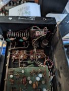
balanced inputs???I didn't get around to powering up for testing but I did open up the unit with DC in one channel and it has some extra bits inside I have not seen before.
Does anyone have any ideas what it is?
Ok just had another look at it, for info left channel is putting out DC.
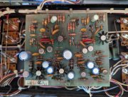
Left channel
Q8 marked 2n1304
Q9 marked 2n1305
Right channel
Q8 marked 2n1308
Q9 marked 2n1307
Does this sound right?
Also there is a resistor in parallel to d8 on both channels
Left is 3.8k and right is 1.5k.
Right channel also has no heatsinks on q7 and q10.
Everything else looks factory or has been done by someone proficient with an iron.
Board is a 14b.
my pl14a says pl14a...Lee
My plan now is to moderately restore one of these for selling. By moderate I mean
Upgrade PS caps
Replace electrolytics on control board
C6 value change and diode addition
Q1,Q2, Q3 and Q4 replacement
Bridge upgrade with WO snubber kit
New MJ21196 outputs
WO LED upgrade board
Don's DCP
Just trying to figure out if this control board needs more work to be usable.
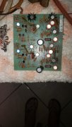
The other control board is a PL14a I believe (marked pl14 on board) but that has seen way better days by its looks.
What are your thoughts?
I didn't get around to powering up for testing but I did open up the unit with DC in one channel and it has some extra bits inside I have not seen before.
Does anyone have any ideas what it is?
Also would I need to replace q8,q9 on both channels?