WOPL 400 4/ powerups went well, one PEM not so much

Joined
Feb 18, 2018
Messages
186
Location
Southern Indiana
Tagline
---6 and 7 days work week, no end in sight
#1
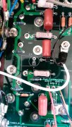
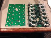
I did not get one PEM soldered correctly on the back of the left board. PEM is in the board straight, but the solder must have been a cold solder.
I did the first powerup, went well. Got to the point, it's time to install to second row of transistors. The top screw on the XQ5 location on the left
board got stuck in the PEM about 3/4 way through and I could not move it.

So I try to back the screw out and the PEM broke lose from the board. AW-Oh, now what?
I did not want to take the boards back out of the chassis, if the PEM broke lose all the way from the board I could have.

So, I got my soldering iron out and soldered the PEM from the front side of the board, got it too were the PEM would not spin,
while I now was able to back the transistor screw out. As far as I can tell, the nylon bushing is still good and not melted.

I finished installing the transistor with the screw still not wanting to go all the way in, so I used washers on the screw.

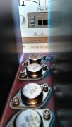
Went on to finish all four powerups.
 

Attachments

WOPL Sniffer

Veteran and General Yakker
Joined
Aug 10, 2015
Messages
11,223
Location
Minnie-Soda
Tagline
Screw it
#3
Looks like more than 1 cold solder joint.

I have at times, ran a 6-32 tape through each pem after soldering them in.
 

roccus

Chief Journeyman
Joined
Jul 4, 2016
Messages
1,112
Location
Maine
Tagline
You'll blow your ears out kid
#5
Yes tap it out you will be good to go, you might want to reflow those solder joints I like to get the solder to flow to the topside of each component as well to assure good solid contact especially on multi layer boards, this will assure way better trouble free performance down the road... just my 2 cents
 
Joined
Feb 18, 2018
Messages
186
Location
Southern Indiana
Tagline
---6 and 7 days work week, no end in sight
#7
Thanks roccus and NavLinear for pointing out the solder joint on both sides of the boards need solder, makes sense.
I will do that tomorrow. I will do all my boards in the future that way with through holes.
 

grapplesaw

Veteran and General Yakker
Joined
Aug 13, 2014
Messages
2,762
Location
Vancouver
Tagline
---
#8
For those who may be interested I got these from Navlinear. They make a good job to hold the Pems flat to the board. Dennis may still have these. I leave the little Kapton seal over the treaded hole till soldering is finished
 

Attachments

laatsch55

Administrator,
Staff member
Joined
Jan 14, 2011
Messages
74,124
Location
Gillette, Wyo.
Tagline
Halfbiass...Electron Herder and Backass Woof
#10
Thanks roccus and NavLinear for pointing out the solder joint on both sides of the boards need solder, makes sense.
I will do that tomorrow. I will do all my boards in the future that way with through holes.

Are you going to try and do that in place, or remove the boards???
 

WOPL Sniffer

Veteran and General Yakker
Joined
Aug 10, 2015
Messages
11,223
Location
Minnie-Soda
Tagline
Screw it
#14
If you are using the PEM holders...... You better crank up the heat on your iron. a screw running through the pem will wick A LOT OF HEAT away from the joint. I don't use them.
 

WOPL Sniffer

Veteran and General Yakker
Joined
Aug 10, 2015
Messages
11,223
Location
Minnie-Soda
Tagline
Screw it
#15
you don't need to try to solder BOTH sides. With the CORRECT amount of heat and the application of flux, the solder will flow and get to both sides.
 
Joined
Feb 18, 2018
Messages
186
Location
Southern Indiana
Tagline
---6 and 7 days work week, no end in sight
#17
HUH??? what screws and washers???
In the pic, I show one output with a screw that has washers under the screw head to hold the output transistor down,
because the screw stopped short of going through the pem. This is the one I have to re-tap and fix, and check all the other pem's.
Just the one is troublesome. Also do some solder work on the other components where there is no solder on the printed side.
So, I'm pulling the outputs and boards back out to fix what I missed the first time. With this said, I already had this powered up
through all four stages of powerups with I thought was good results. Just want to make sure all is well for the next 40 years of
amp life.
 

Attachments

Joined
Feb 18, 2018
Messages
186
Location
Southern Indiana
Tagline
---6 and 7 days work week, no end in sight
#18
In the pic, I show one output with a screw that has washers under the screw head to hold the output transistor down,
because the screw stopped short of going through the pem. This is the one I have to re-tap and fix, and check all the other pem's.
Just the one is troublesome. Also do some solder work on the other components where there is no solder on the printed side.
So, I'm pulling the outputs and boards back out to fix what I missed the first time. With this said, I already had this powered up
through all four stages of powerups with I thought was good results. Just want to make sure all is well for the next 40 years of
amp life.
Well, I guess I made that a lot longer answer than it should have been, sorry bout that, Perry...……...
 
Last edited:
Top