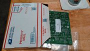
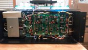
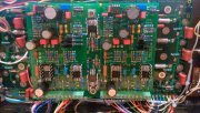
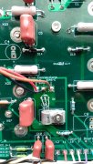
WOPL 400 4/ powerups went well, one PEM not so much

NavLinear

Veteran and General Yakker
Joined
Apr 12, 2012
Messages
6,022
Location
SoCal
#21
If you are using the PEM holders...... You better crank up the heat on your iron. a screw running through the pem will wick A LOT OF HEAT away from the joint. I don't use them.
Hey Perry,

The PEM clamp screws are nylon and the heat transfer is minimal. Lee, myself and a couple of others have done multiple backplane boards using the clamps and have replaced a nylon screw or two over the years due to heat but the heat transfer delta between using the PEM clamps and no clamp is minimal.
 
Last edited:

Gepetto

Administrator
Staff member
Joined
May 15, 2011
Messages
13,473
Location
Sterling, MA
Tagline
Old 'Arn Enthusiast
#23
You need to wait long enough for the solder to flow easily after heating up the solder joint. There is a lot of thermal mass on most of the connections to these boards.
 
Joined
Feb 18, 2018
Messages
186
Location
Southern Indiana
Tagline
---6 and 7 days work week, no end in sight
#25
Ok, I got the boards back in after re-soldering all the PEM's, and all other components with good solder flow.
Made sure to run a 6-32 tap through the PEM's before reinstall. This time, no issues with output Transistors
screws not going all the way through PEM's.
Got the powerups to go without a hitch. I feel a lot better about the WOPL 400 build now.
I think my control board is due in today.

L board: R board:
+82.7 +82.7
-82.6 -82.6
output/ground output/ground
00.0 00.0
 

kingman

Journeyman
Joined
Mar 22, 2017
Messages
93
Tagline
---
#27
It was about a year ago when I did these boards, if my memory is correct, I had my solder iron set at 750 degrees.
Maybe flux and solder flow was wrong.
All the boards for the new Carver 275 tube amp were soldered at 750 and even higher. The heat allowed the solder to flow through to the other side of the board.
 
Joined
Feb 18, 2018
Messages
186
Location
Southern Indiana
Tagline
---6 and 7 days work week, no end in sight
#28
The first time you hear the WOPL, it will be worth it. .
Well, I'm taking my time and being patient about it. One has got to be even after getting the Backplane boards in
the chassis to find out, one has to pull it all back out, fix what was over looked. Lesson learned on my part.

I believe you when you say worth it.
 
Joined
Feb 18, 2018
Messages
186
Location
Southern Indiana
Tagline
---6 and 7 days work week, no end in sight
#29
All the boards for the new Carver 275 tube amp were soldered at 750 and even higher. The heat allowed the solder to flow through to the other side of the board.
I'm 100% believer on high heat on these boards, they are very robust and built well.
 

laatsch55

Administrator,
Staff member
Joined
Jan 14, 2011
Messages
74,124
Location
Gillette, Wyo.
Tagline
Halfbiass...Electron Herder and Backass Woof
#30
Well, I'm taking my time and being patient about it. One has got to be even after getting the Backplane boards in
the chassis to find out, one has to pull it all back out, fix what was over looked. Lesson learned on my part.

I believe you when you say worth it.

They are not an acquired taste, they slap you in the face...
 

Northwinds

Veteran and General Yakker
Joined
Mar 18, 2013
Messages
7,543
Location
Coventry, CT
Tagline
Fondler errrr... fan of all Nav's avatars
#34
Yes tap it out you will be good to go, you might want to reflow those solder joints I like to get the solder to flow to the topside of each component as well to assure good solid contact especially on multi layer boards, this will assure way better trouble free performance down the road... just my 2 cents
Good to see you here man!!!
 
Joined
Feb 18, 2018
Messages
186
Location
Southern Indiana
Tagline
---6 and 7 days work week, no end in sight
#36
Now I got my control board built and installed in the amp. Powerup went good, nothing smoking or
blew up. On full line voltage now. Bias adjustments not going so well.
Left Bias adjustment reading .000 no matter where adjustment is. Right Bias adjustment reads .156 constantly
no matter where adjustment is.
 

Attachments

laatsch55

Administrator,
Staff member
Joined
Jan 14, 2011
Messages
74,124
Location
Gillette, Wyo.
Tagline
Halfbiass...Electron Herder and Backass Woof
#37
Are the bias transistors soldered in the 3403 holes or the 5022 holes? Bias transistor wire reversals going to the driver board??
 

Gepetto

Administrator
Staff member
Joined
May 15, 2011
Messages
13,473
Location
Sterling, MA
Tagline
Old 'Arn Enthusiast
#39
I got them in the 5022 holes.
Yes but did you replace the original 2N3403 that was in the P strap with the 2N5088?

If this, then the leads are in the correct holes.


Or did you leave the 2N3403 installed in the P strap.

If the latter, then the leads are in the wrong holes.
 

Gepetto

Administrator
Staff member
Joined
May 15, 2011
Messages
13,473
Location
Sterling, MA
Tagline
Old 'Arn Enthusiast
#40
Now I got my control board built and installed in the amp. Powerup went good, nothing smoking or
blew up. On full line voltage now. Bias adjustments not going so well.
Left Bias adjustment reading .000 no matter where adjustment is. Right Bias adjustment reads .156 constantly
no matter where adjustment is.
Is your output reading 0.000V or very close to it on both channels?
 
Top