If you want to take the rust off the screws, recommend you use the electrolysis method. It works.

You are using an out of date browser. It may not display this or other websites correctly.
You should upgrade or use an alternative browser.
You should upgrade or use an alternative browser.
Sutton's Phased Linear White Oaked 1000 Rigg #2
- Thread starter laatsch55
- Start date
- Joined
- Jan 14, 2011
- Messages
- 75,894
- Location
- Gillette, Wyo.
- Tagline
- Halfbiass...Electron Herder and Backass Woof
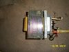
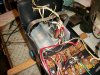
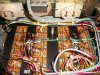
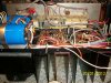
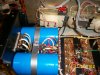
This is the 700 with the skewed transformer laminations. So...... out it comes.
Attachments

- Joined
- Jan 14, 2011
- Messages
- 75,894
- Location
- Gillette, Wyo.
- Tagline
- Halfbiass...Electron Herder and Backass Woof
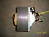
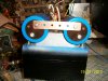
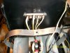
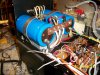
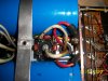
Got the transformer straightened out, painted, new bus bar for the caps ( 1/8 inch by 3/4 inch) new wires run for the DC boards, new wires for Joe's board, separate power and grounds to both sides, speaker posts changed out to some that will take the stand-offs for the DC board, and will be moving the AC in and AC fuseholder to the transformer side.
Attachments
mlucitt
Veteran and General Yakker
Now that is what I call an amplifier overhaul! Lee you could sell that buss bar for the weight of the copper, it's probably good for 200 Amps?
- Joined
- Jan 14, 2011
- Messages
- 75,894
- Location
- Gillette, Wyo.
- Tagline
- Halfbiass...Electron Herder and Backass Woof
You should see my 1000 amp busbar, 1/4 inch by 2 inch, and they are 5 feet long. This bus bar was cut from the smallest i have.
- Joined
- Jan 14, 2011
- Messages
- 75,894
- Location
- Gillette, Wyo.
- Tagline
- Halfbiass...Electron Herder and Backass Woof
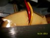
The cool thing about this busbar is it's drilled and tapped every 1/2 inch with a 10-32 thd.
- Joined
- Jan 14, 2011
- Messages
- 75,894
- Location
- Gillette, Wyo.
- Tagline
- Halfbiass...Electron Herder and Backass Woof
mlucitt
Veteran and General Yakker
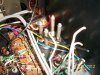
Playing with those solid conductors coming off the transformer is fun, isn't it? Which caps are you using to bypass the bridge rectifier? The amp looks good, really starting to take shape, the before and after shots will be dramatic.
- Joined
- Jan 14, 2011
- Messages
- 75,894
- Location
- Gillette, Wyo.
- Tagline
- Halfbiass...Electron Herder and Backass Woof
mlucitt
Veteran and General Yakker
What's up with that funky light board? It should be greenish, no?
- Joined
- Jan 14, 2011
- Messages
- 75,894
- Location
- Gillette, Wyo.
- Tagline
- Halfbiass...Electron Herder and Backass Woof
It will be Mark. That's usually the last thing I do. The faceplate gets so much handling during the work, I let the old one take the punishment.
mlucitt
Veteran and General Yakker
Good idea, I thought you would have stripped it off and cut the wires rather than having to fool with it because you basically re-wired that amp. Looking good.
- Joined
- Jan 14, 2011
- Messages
- 75,894
- Location
- Gillette, Wyo.
- Tagline
- Halfbiass...Electron Herder and Backass Woof
I usually do, but this one had enough shielded that i could work it without too much trouble.
mlucitt
Veteran and General Yakker
My 700B was like that. I ended up cutting out about 8" of shielded cable when I changed out the level pots and I could have cut more but I wanted to keep the L and R cables the same length.
- Joined
- Jan 14, 2011
- Messages
- 75,894
- Location
- Gillette, Wyo.
- Tagline
- Halfbiass...Electron Herder and Backass Woof
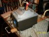
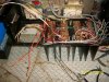
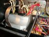
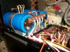
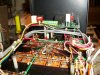
It seems I have to be in a certain frame of bmind to wire on one of these puppies. I am done with the transformer end and I'm pretty tickled the way it turned out.
Attachments
- Joined
- Jan 14, 2011
- Messages
- 75,894
- Location
- Gillette, Wyo.
- Tagline
- Halfbiass...Electron Herder and Backass Woof
speakerman1
Honorary Forum "Larrt" (ornery too)
- Joined
- Jun 12, 2010
- Messages
- 12,037
- Location
- OZONE ALLEY MARS (Visitor)
- Tagline
- Wasted Days and Wasted Nights
What are you doing up?
Larry
Larry
mlucitt
Veteran and General Yakker
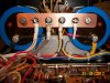
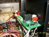
Lee, That is some serious heatshrink on the transformer output common wires. I would have thought that the outputs would be the red ones and the white ones would be the commons, but I guess it does not matter as long as the two phases are correct.
So that output protect board opperates at full rail voltage of 200VDC? Wow! I will be interested to hear how well the tests go. Rod Elliott wants me to test his board by putting rail voltage through a 100K resistor to the inputs to make sure the relays open when the board sees DC. OK, I am scared to do that, maybe a 9V battery... What is your plan to test the DC protect part of the circuit?
I really like the way you wired the bulk storage caps, very neat.
Skratch
Chief Journeyman
Hi Sutton Was in your area last week, Rural Retreat, beautiful country
- Joined
- Jan 14, 2011
- Messages
- 75,894
- Location
- Gillette, Wyo.
- Tagline
- Halfbiass...Electron Herder and Backass Woof
No Mark, the board gets voltage on the AC side of the BR. For a test I usually run a strong square wave and that does it. I suppose we should get with Don about parameters for a standard test that would at least make someone comfortable about handing this amp some tasty 8K worth of speakers. AND. it would be nice to have some numbers that say this is "bad" or "good".