Russ' 700B Wopl

Done wiring the board.....time to power up...
 

Attachments

  • Russ's Pics 018.jpg
    Russ's Pics 018.jpg
    103.4 KB · Views: 18
A very UNEVENTFUL power up. Offset is .001 on the left and .000 on the right. Bias started at .252 on the minimum setting and right at 7-o'clock at 350mv preliminary setting....looking ood so far.
 
An interesting scope shot of the left channel. 600hz, 270 mv input and the heatsinks are getting hot. Right channel is good to go...
 

Attachments

  • Russ's Pics 019.jpg
    Russ's Pics 019.jpg
    91.6 KB · Views: 21
200 watts out.......
 

Attachments

  • Russ's Pics 020.jpg
    Russ's Pics 020.jpg
    91.4 KB · Views: 23
THD & N is a little high on the left channel, .221% and I can feel some oscillation in the left channel heatsinks...


That wasn't oscillations, but somebody is no longer looking for it now. :sign6:
 
Last edited:
Residual noise is not good either, 1.6mv on the left and 1.8mv on the right...
 
So, I'm sure ya'll have the burning question----" Is 1.6 mv and 1.8mv residual noise audible?" Why yes, yes it is .....

I don't think we've discussed having to flip the plug on a WOPL, I know we have on a stocker. With the IEC plugs that's not possible until we cut the ground lug....

I have switched the plugs on almost every amp I've done and there has been no difference either way. Then again I've not seen a set of pots wired like this. This amp tested very good in the noise department before the conversion, so I thought I would leave the pots alone.

As soon as Chris Isaack finishes up I'll put it up on the bench and document how the pots are wired.
 

Attachments

  • Russ's Pics 021.jpg
    Russ's Pics 021.jpg
    95.1 KB · Views: 27
Last edited:
Like so.......


Joe, does your Spice model predict the theoretical noise floor???
 

Attachments

  • Russ's Pics 026.jpg
    Russ's Pics 026.jpg
    99.5 KB · Views: 25
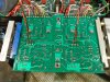
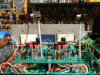
The pot wiring goes like this........signal correct to the jack center tab, shields are then twisted together then soldered to the ground plate on the rCA jacks. It is two conductor and shield. the 2nd conductor is cut off at the end of the insulation. At the pots the signal wires go to the center tab and one side, the other side the shield wires are terminated, the second conductor is cut off at the insulation. The control board end has the signal wire and the second conductor is cut off at the insulation. The shield is soldered to the ground pad. This to me says a ground loop is possible.
In addition to this the 220 ohm resistors come off the output tabs on the slide switch to chassis ground. There is also a solid wire from the rCA ground plane to the slide switch ground to chassis ground., another no-no.

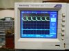
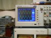
Why did I leave it this way you ask?? To see if it would make noise!!

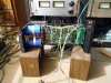
To prove this right quick I have a pair of jacks I will solder directly to the board and throw it back on the AP.....Just cause, always wanted to do that to see just how low the noise would go without the input wiring in the chassis....
Lee there is no easy way to ground the pot cicuit. I have kept my wiring to the way you are doing it

I have dropped the high pass filter, both resistor and cap from my builds
 
That's the point Glen, not grounding the pot circuit is the goal...


Figures now...
 

Attachments

  • Russ's Pics 027.jpg
    Russ's Pics 027.jpg
    80.6 KB · Views: 19
That's the point Glen, not grounding the pot circuit is the goal...


Figures now...
I went crazy on the D500 because I lifted the ground by isolation get the RCA jacks as done on this setup. The RCA Jack used to screw into the heat sink and created the ground point for the stock board. By doing this the stock board had no ground and would not work. I ended up taking a wire from the ground connection for the input to the board back to the star ground.
 
Were you measuring the noise as you went?
Not by itself. Did N+THD and was happy with the results. I will start measuring more this from now on. I need a Audio Presision unit. I been waiting for an affordable sound card software setup to get good.
 
I ran my Fluke thermocouple to the Q1 heatsink and I am reading 170 deg F.....
 
Back
Top