Russ' 700B Wopl

laatsch55

Administrator,
Staff member
Joined
Jan 14, 2011
Messages
75,005
Location
Gillette, Wyo.
Tagline
Halfbiass...Electron Herder and Backass Woof
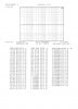
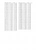
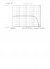
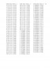
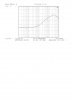
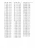
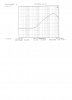
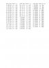
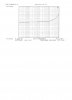
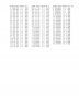
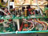
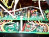
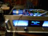
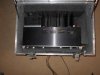
Before I button this puppy up and cabbage case it I thought I would take a couple more pics of the pot wiring. I did these a little different. I know this had an effect on the noise figures, which in this amp were excellent. The UNWEIGHTED measurements from 10hz to 80Khz were only 10 to 20 microvolts more than the IEC A Weighted 10hz to 31.5Khz so something made a difference.

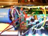
I tried several different runs of the shielded cable. And while hooked up to the AP , moved the shielded around. At one point the noise figures dropped by half. That is the configuration it is in now. Coming straight out of the RCA jacks to the DCP then arcing over the driver board to each pot. NOW , the big difference. I went straight from the pots to the TOP OF THE DRIVER board. Yes, removing the faceplate would require either de-mounting the pots or desoldering the input wiring from the boards. I think the improvement in noise levels warrant that little inconvenience...the average user won't ever have the covers off anyway and anybody working on it won't be inconvenienced that much.

Being a bit philosophical this morning I can't help but wonder, that in 30 to 40 years ( if music is still produced through one of these) members of some obscure online forum will be opening up their WOPL's and comparing builds from the A boards through the M boards thinking" What in the F%^& were these folks thinking?" " Couldn't they make up their minds?'.......To answer that question before they ask it...." No, we couldn't, because Joe was never satisfied and refused to sit on his laurels"

The latest measurements of noise in Justin Case's 400 were phenomenal, those unweighted figures also tracked just 10 to 20 microvolts higher meaning that both channels were under 200uv. Can we get a 700 under 200?? Maybe, maybe not, but that don't stop us from trying. It's also possible that any improvements in noise figure will require removing the power supply from the chassis altogether, and I still plan on that this coming winter, not even the thermoswitch will be internal on that one....
I feel that having an engineer of Joe's caliber doing what he does to these amps is a gift to audio we can all appreciate...I for one I'm grateful to get to work with him in some capacity. Just for shits and giggles I put a Spec 2 in rotation the other day........it did not stay there.......


Attachments

laatsch55

Administrator,
Staff member
Joined
Jan 14, 2011
Messages
75,005
Location
Gillette, Wyo.
Tagline
Halfbiass...Electron Herder and Backass Woof
Packed and ready....man, for my money, this is the only way to ship an amp. Kinda pricey, IIRC, the cabbage case was 257.00, but well worth it. Haven't had a shipping damage claim since I started using it. AND it only takes 2 minutes to pack, that in itself is worth it....
 

Attachments

NavLinear

Veteran and General Yakker
Joined
Apr 12, 2012
Messages
6,061
Location
SoCal
Really nice work Lee on this one as always. I've been reading this thread for it's duration - just haven't chimed in.

I was wondering how you terminate the shields - or do you leave them floating? It was cool that you could move the cables and test real time with the AP to see the effects of different cable locations/routing. The noise was in the mud but halving it is phenomenal. Cool shit.

There has to be a better way to hold those meters in place using the existing bezel bracket.
 

laatsch55

Administrator,
Staff member
Joined
Jan 14, 2011
Messages
75,005
Location
Gillette, Wyo.
Tagline
Halfbiass...Electron Herder and Backass Woof
Shields are tied to the RCA jack copper plate, then the 3rd post on the pot and terminated at the ground pad on the driver board. The 2nd wire of the shielded pair is cut at the outer cover trim line and not used.

On the meter mounts....if we could silicone the metal bezel to the faceplate we could hold the meter in place with a FaboNav printed bracket that spanned the meter then, hooked in the slots in the bezels and had holes that fit over the plus/minus terminals. It wouldn't take much to hold the meters themselves if the metal bezels could be held separately....
 

laatsch55

Administrator,
Staff member
Joined
Jan 14, 2011
Messages
75,005
Location
Gillette, Wyo.
Tagline
Halfbiass...Electron Herder and Backass Woof
Or if the plastic turned out to be too flimsey, a metal strap with enlarged holes that went over the meter terminals with a nylon bushing to isolate the strap....
 

laatsch55

Administrator,
Staff member
Joined
Jan 14, 2011
Messages
75,005
Location
Gillette, Wyo.
Tagline
Halfbiass...Electron Herder and Backass Woof
The limiting factor will be the length of the threaded terminals on the back of the meters.....not much to work with there....
 

Northwinds

Veteran and General Yakker
Joined
Mar 18, 2013
Messages
7,566
Location
Coventry, CT
Tagline
Fondler errrr... fan of all Nav's avatars
There has to be a better way to hold those meters in place using the existing bezel bracket
Agreed, the silicone looks like a cob job. The little meter holders seem to work great as long as you keep the straight up and down, problems with meter slippage happen when the little clamps get slanted. What if you just put a drop of silicone in each corner of the bezel and then install the bezel, then wipe off any excess that gets squeezed out?
 

laatsch55

Administrator,
Staff member
Joined
Jan 14, 2011
Messages
75,005
Location
Gillette, Wyo.
Tagline
Halfbiass...Electron Herder and Backass Woof
Until we come up with another way the Silicon hedges our bets. And they don't always stay if the jam screws are straight. Depends on the angle of the jam straps and the distortion of the slots in the bezels. Nothing about the whole mess is copesetic...
 

Northwinds

Veteran and General Yakker
Joined
Mar 18, 2013
Messages
7,566
Location
Coventry, CT
Tagline
Fondler errrr... fan of all Nav's avatars
I suppose a zip tie would work if fed through the jam screw slots. That way when you tighten it, the zip tie rests across the back of the round part of the meter instead of the jam screws pushing in on the sides which can cause meter binding if too tight
 

grapplesaw

Veteran and General Yakker
Joined
Aug 13, 2014
Messages
2,778
Location
Vancouver
Tagline
---
Shields are tied to the RCA jack copper plate, then the 3rd post on the pot and terminated at the ground pad on the driver board. The 2nd wire of the shielded pair is cut at the outer cover trim line and not used.

On the meter mounts....if we could silicone the metal bezel to the faceplate we could hold the meter in place with a FaboNav printed bracket that spanned the meter then, hooked in the slots in the bezels and had holes that fit over the plus/minus terminals. It wouldn't take much to hold the meters themselves if the metal bezels could be held separately....

Lee did you ever try taking the sheild only to the star ground on the power caps and not bond the shield to the RCA ground leaving the RCA in and ground plate bonded only through the black wire to the pots and then to the control board??
 
Top