PL700 Rebuild

Sunnbobb

Journeyman
Joined
May 25, 2023
Messages
228
Location
Mount Vernon, WA
Tagline
Bikes, baseball and big amps.
First off the fact that Joe includes the schematic for his proprietary board makes trouble shooting so much easier, thank you sir. Verified clean signal generator input to rca jacks, input to control board clean, input both inverting and non inverting pins 2 and 3 on the op amp clean, pin 7 15.1v pin 4 -15.1v. However output on pin 6 was a disaster on either channel, wish I could hold phone oscope probe and take a picture all at the same time. basically a lot of hash and minimal waveform. anyways need to order some op134's.
Can only blame myself, even with checking followed the wrong back plane output transistor numbering sequence and probably stressed those poor op amps by doing so even on a dbt startup. Stay tuned for the next installment once Mouser gets me the op amps.
Joe has the best product support I have ever seen!
 

Overundr1

Journeyman
Joined
Sep 12, 2024
Messages
175
The new IC cleaned up the input side of things however really getting frustrated that I cannot figure this out on my own. Have no collector voltage to banks two and four. Show a solid -80V on pin 3 of the WOPL control board yet nothing on the collectors. replaced the two 1N4004 diodes on each side, verified the two 150ohm resistors that connect the pin three purple wire to the rca driver transistor, pulled and verified the driver transistor both sides and still no voltage. Confirmed -80v at fuse terminals that feed bank two as well. Could use a helping pair of eyes pweeeze :)
 

Gepetto

Administrator
Staff member
Joined
May 15, 2011
Messages
14,014
Location
Sterling, MA
Tagline
Old 'Arn Enthusiast
The new IC cleaned up the input side of things however really getting frustrated that I cannot figure this out on my own. Have no collector voltage to banks two and four. Show a solid -80V on pin 3 of the WOPL control board yet nothing on the collectors. replaced the two 1N4004 diodes on each side, verified the two 150ohm resistors that connect the pin three purple wire to the rca driver transistor, pulled and verified the driver transistor both sides and still no voltage. Confirmed -80v at fuse terminals that feed bank two as well. Could use a helping pair of eyes pweeeze :)
Are you counting the first bank as that which is next to the transformer?

If yes, then banks 2 and 4 are the quasi comp construct and the collectors of these banks are the amp output. B- is applied to the emitter resistors on these banks. The collectors will be very near zero with no input to the amp.

B+ is applied to the collectors on banks 1 and 3. Those are emitter follower outputs. Very different from the quasi banks.

One of the several downsides of quasi-comp construction is that the collector cans are swinging with the output signal, dragging along the capacitance associated with the can area up against a grounded heatsink. This does not occur on the positive half, columns 1 and 3.


1733249068291.png
 
Last edited:

Overundr1

Journeyman
Joined
Sep 12, 2024
Messages
175
That explanation was most helpful. Do have (on limiter) -81v at the indicated positions (the +81v had already been verified)
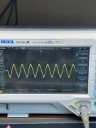
Checked output from control board 6L and 6R and do have a clean scope sine wave. Lol even cleaner if I would remember to turn the intensity down and use the focus once in a while sheesh.
1733262206039.jpeg

Removed output wires from the speaker relay and also have clean signal not withstanding my sloppy methodology.

1733262263253.jpeg

However the minute I run the output through the relay board everything goes to pieces, especially at frequencies below @240hz. Somebody mentioned ground loops, tomorrow will try and sort that out. The three pure white wires on the relay pins 2,4,6 all go to the buss bar between the two main caps btw. The scope trace when everything is wired up as read off the positive speaker post on the relay board shows terrible hash and waveform flutter. Suppose I could wire one channel up directly to the speaker out as originally designed and try that as well.
Meanwhile saving the pennies to do the full conversion but sure would like to get this working first.
 

Gepetto

Administrator
Staff member
Joined
May 15, 2011
Messages
14,014
Location
Sterling, MA
Tagline
Old 'Arn Enthusiast
That explanation was most helpful. Do have (on limiter) -81v at the indicated positions (the +81v had already been verified)
Checked output from control board 6L and 6R and do have a clean scope sine wave. Lol even cleaner if I would remember to turn the intensity down and use the focus once in a while sheesh.
View attachment 84474

Removed output wires from the speaker relay and also have clean signal not withstanding my sloppy methodology.

View attachment 84475

However the minute I run the output through the relay board everything goes to pieces, especially at frequencies below @240hz. Somebody mentioned ground loops, tomorrow will try and sort that out. The three pure white wires on the relay pins 2,4,6 all go to the buss bar between the two main caps btw. The scope trace when everything is wired up as read off the positive speaker post on the relay board shows terrible hash and waveform flutter. Suppose I could wire one channel up directly to the speaker out as originally designed and try that as well.
Meanwhile saving the pennies to do the full conversion but sure would like to get this working first.
Is your copper plate under the RCA jacks fully isolated from the chassis? It is essential...
 

Overundr1

Journeyman
Joined
Sep 12, 2024
Messages
175
Copper plate isolated from ground. Verified input wire grounds isolated when unhooked from 2L or 2R. However those two points on the control board both show grounding.
 

Hexis22

Chief Journeyman
Joined
Dec 28, 2022
Messages
713
Location
Wisconsin
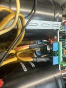
Can you show how the two Red wires are terminated on the other end near the rectifier.


Also, did you correct the small White wire termination at the power supply cap?


Sunnbobb

Journeyman
Joined
May 25, 2023
Messages
228
Location
Mount Vernon, WA
Tagline
Bikes, baseball and big amps.
Just curious. The speaker protect board has a Zobel network. Does the White Oak board have one also? And would that be a problem? I remember removing the zobel from Don's speaker protection board on a couple of 400 rebuilds.
 

laatsch55

Administrator,
Staff member
Joined
Jan 14, 2011
Messages
74,883
Location
Gillette, Wyo.
Tagline
Halfbiass...Electron Herder and Backass Woof
I have just about everything Lee. Pretty sure that I know as much about PL 400/700 amps as the founder did/does. I documented a lot more.

Nominating this one as quote of the year.......it'll go on my siggie at least...
 

Overundr1

Journeyman
Joined
Sep 12, 2024
Messages
175
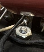
That is a ground point and checked to ensure wire was not touching the hold down nut
Good observation though, more eyes the better.
 

Overundr1

Journeyman
Joined
Sep 12, 2024
Messages
175
Before I start hacking away at things, how about a 1N4007 diode anode on each ground wire from pins 2 and 4 then combining those two wires at a frame ground point away from the buss bar. Also have an exact 4uf axial np set of caps coming instead of the ecq 4.7uf's. Spent quite a while going over boards today, could not spot any solder bridges or loose connections, interesting to me that I get a solid output waveform from the amp when NOT attached to the speaker relay and hash/noise that increases with a decrease in frequency starting around 240hz and lower.
During the testing I also have the meters disconnected as well, infact at one point had all the lamps out of circuit as well in case there was some sort of backfeed going on.
 

Hexis22

Chief Journeyman
Joined
Dec 28, 2022
Messages
713
Location
Wisconsin
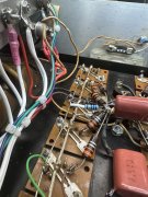
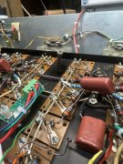
Not likely the main cause of your issues, but something you should correct involves multiple buss bar chassis grounds (see picture below).

The original factory chassis ground wire is the small white wire poorly attached to the neg terminal of the B+ rail capacitor. This wire runs down the center of the backplane attaching to chassis ground terminals near the new capacitors you updated.

The second ground wire you added is terminated using one of the non isolated transformer mounting bolts, not ideal from a noise perspective.

 
Top