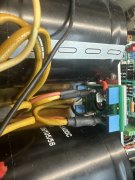
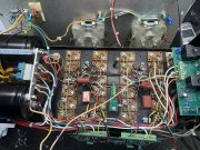
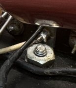
That explanation was most helpful. Do have (on limiter) -81v at the indicated positions (the +81v had already been verified)
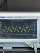
Checked output from control board 6L and 6R and do have a clean scope sine wave. Lol even cleaner if I would remember to turn the intensity down and use the focus once in a while sheesh.
View attachment 84474
Removed output wires from the speaker relay and also have clean signal not withstanding my sloppy methodology.
View attachment 84475
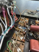
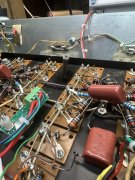
However the minute I run the output through the relay board everything goes to pieces, especially at frequencies below @240hz. Somebody mentioned ground loops, tomorrow will try and sort that out. The three pure white wires on the relay pins 2,4,6 all go to the buss bar between the two main caps btw. The scope trace when everything is wired up as read off the positive speaker post on the relay board shows terrible hash and waveform flutter. Suppose I could wire one channel up directly to the speaker out as originally designed and try that as well.
Meanwhile saving the pennies to do the full conversion but sure would like to get this working first.


