PL700 Rebuild

J!m

Veteran and General Yakker
Joined
Dec 24, 2019
Messages
10,831
Location
Connecticut
Tagline
BOT
Well, yeah.

Once people figure out it works, they ban it.

What about (red can) Brakleen? It's chlorinated! MMMMmmmmmmm! (I even use it for dry cleaning stains from shirts!)
 

Overundr1

Journeyman
Joined
Sep 12, 2024
Messages
175
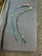
Think this is the last of the preparation work. Finished up the temp compensating transistor assembly. time to remove the old control board and wire up the new one unless members remind me of something I missed. Red=E Black= B Green = C
Leads intentionally left long till I get things all in place in the chassis. The transistors are held in place with a drop of glue along with the tension of the P-strap to ensure no lead to case or chassis shorts.

1731015197288.jpeg
 

Overundr1

Journeyman
Joined
Sep 12, 2024
Messages
175
Yes sir those are either aluminum or mild steel. Forgot I had a couple that were oem straps on Sansui F-2980 temp bias transistors mounted to the pre driver heatsinks so was able to use those with the new transistors
 

Overundr1

Journeyman
Joined
Sep 12, 2024
Messages
175
Funny how I have acquired boxes and boxes of spare Sansui parts over the last twenty years or so. Guess it does help to specialize in one manufacturer's designs
 

Overundr1

Journeyman
Joined
Sep 12, 2024
Messages
175
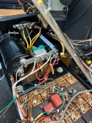
Time for a wiring check - - -
Left cap + is up
White wire on + connector end of buss bar goes to speaker relay pin 6
Two white wires on buss bar with green mark go to relay board ground position 2 and 4

1731087220488.jpeg

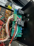
Relay board position 1 left speaker white output wire from backplane
Relay board position 3 right speaker white with red stripe output wire from backplane
Relay position 2 and 4 are the new white/green stripe wires to buss bar shown above
Relay position 5 and 7 are the new brown wires from ac points on new rectifier
Relay position six has three wires, a thin white/red wire that heads to new control board, a new white ground wire to ground of input jack and the original white wire that connects to the left main cap + (upper) terminal.
1731087468737.jpeg

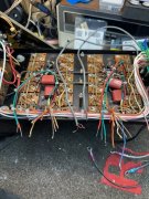
And the backplane. New center board mounts installed, thermal compensation transistors mounted (green/black/red wires)
Input wires from new input jacks (grey) left and right
The thin white wire from relay pin 6 on the far right
The new meter wiring assembly on the work surface below the frame.
Every wire that enters a phoenix connector will be/already has been tinned to prevent strands from getting into mischief.
If I have made an mistake please show me the error of my ways otherwise will continue with the new WOPL board install.
Also, I did order a new wiring kit along with the board and seriously thinking of taking the time to replace all those old crusty hook up wires from the backplane board with nice color co-ordinated new ones.

1731087758227.jpeg
 

Overundr1

Journeyman
Joined
Sep 12, 2024
Messages
175
And somehow a piece of yellow masking tape is rudely posing on the speaker relay board and will be removed immediately.
 

Hexis22

Chief Journeyman
Joined
Dec 28, 2022
Messages
706
Location
Wisconsin
Relay position six has three wires, a thin white/red wire that heads to new control board, a new white ground wire to ground of input jack and the original white wire that connects to the left main cap + (upper) terminal.
All grounds should terminate back to the main capacitor buss bar.

Position six on the relay board should only have one ground wire back to the buss bar.

Remove and discard the wire connected to the copper plate between RCA inputs and relay board. RCA grounds connect to the new control board (pin 2 on each side).

Pin 5 of each control board Phoenix connector should have dedicated wires back to the buss bar.
 

Overundr1

Journeyman
Joined
Sep 12, 2024
Messages
175
I am starting to understand why folks do the full WOPL upgrade. That backplane is unreal, yuck. Anyways for now will carry on. Fixed the wiring as detailed above. Now ready to install new control board and darned if I can find anywhere on the schematics how those output sockets are numbered. So perhaps yet another helping hand with the picture I posted above?
 

Overundr1

Journeyman
Joined
Sep 12, 2024
Messages
175
Also think I need to change out the original wires for WOPL wires so the hooking up of the board goes without any magic smoke production once I get the output sockets identified.
 

Gepetto

Administrator
Staff member
Joined
May 15, 2011
Messages
14,008
Location
Sterling, MA
Tagline
Old 'Arn Enthusiast
I am starting to understand why folks do the full WOPL upgrade. That backplane is unreal, yuck. Anyways for now will carry on. Fixed the wiring as detailed above. Now ready to install new control board and darned if I can find anywhere on the schematics how those output sockets are numbered. So perhaps yet another helping hand with the picture I posted above?
The attached should be clear enough Lee...
 

Attachments

Top