PL700 Rebuild

Gepetto

Administrator
Staff member
Joined
May 15, 2011
Messages
14,020
Location
Sterling, MA
Tagline
Old 'Arn Enthusiast
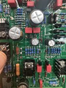
Before I start hacking away at things, how about a 1N4007 diode anode on each ground wire from pins 2 and 4 then combining those two wires at a frame ground point away from the buss bar. Also have an exact 4uf axial np set of caps coming instead of the ecq 4.7uf's. Spent quite a while going over boards today, could not spot any solder bridges or loose connections, interesting to me that I get a solid output waveform from the amp when NOT attached to the speaker relay and hash/noise that increases with a decrease in frequency starting around 240hz and lower.
During the testing I also have the meters disconnected as well, infact at one point had all the lamps out of circuit as well in case there was some sort of backfeed going on.
Lee
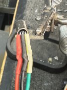
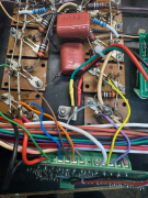
I cannot tell for sure how you have the bias transistors wired from a color code perspective. Is the transistor a 2N5088? Is its flat facing the chassis? If yes, then emitter is green wire? Base is black wire? Red is collector wire?
 

Overundr1

Journeyman
Joined
Sep 12, 2024
Messages
175
Will fix ground wire attach point, remove the extra wire that was suggested a few pages back and verify e-b-c connections on the 2N5088 thermal compensation transistor shortly :)
 

Gepetto

Administrator
Staff member
Joined
May 15, 2011
Messages
14,020
Location
Sterling, MA
Tagline
Old 'Arn Enthusiast
Will fix ground wire attach point, remove the extra wire that was suggested a few pages back and verify e-b-c connections on the 2N5088 thermal compensation transistor shortly :)
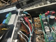
The second wire that Eric pointed out that goes to the transformer bolt is not necessary. One and only one DC ground should tie to chassis ground.
 

Overundr1

Journeyman
Joined
Sep 12, 2024
Messages
175
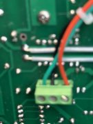
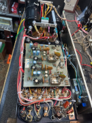
Lets make absolutely sure I have the control board wired correctly to the backplane. Remember this is the first version of the PL-700 so rather than confuse things lets go with the rca6654's are in all four bottom rows (closest to control board connector), the rest going up to the top are MJ21196's on silipads. Bank 1 is closest to transformer
L1 Input +
L2 input ground
L3 Purple Base of RCA 6654 bank 2
L4 Yellow collector first MJ21196 bank 2
L5 White to buss bar between main caps
L6 open since this is a quasi-complimentary setup
L7 Grey to collector RCA 6654 bank 2
L8 Orange collector of rca6654 bank 1
L9 Brown emitter of first MJ21196 bank 1
L10 Blue base rca 6654 bank 1
L11 Green base first MJ21196 bank 1
L12 Main cap +
L13 Main cap -

1733363996899.png
 

Overundr1

Journeyman
Joined
Sep 12, 2024
Messages
175
Is there a safe upper limit for idle bias? Wondering if the mj21196’s are causing extreme crossover distortion?
 

Gepetto

Administrator
Staff member
Joined
May 15, 2011
Messages
14,020
Location
Sterling, MA
Tagline
Old 'Arn Enthusiast
Lee have you verified your +/-15V on each channel? This has not been mentioned in this thread.
 

Overundr1

Journeyman
Joined
Sep 12, 2024
Messages
175
Not sure, at the moment removing all outputs, cleaning each socket with dental cleaning brushes, tightening them slightly and re installing just in case the distortion artifacts are due to loose or dirty to-3 sockets.
Will test again for the 3Mhz once completed sir.
 

Gepetto

Administrator
Staff member
Joined
May 15, 2011
Messages
14,020
Location
Sterling, MA
Tagline
Old 'Arn Enthusiast
Not sure, at the moment removing all outputs, cleaning each socket with dental cleaning brushes, tightening them slightly and re installing just in case the distortion artifacts are due to loose or dirty to-3 sockets.
Will test again for the 3Mhz once completed sir.
I recommend that you install only the bottom row devices and check things out. It will help to isolate where your issues may lie. The amp will work perfectly as an amp with only the bottom row installed. It won't drive much but it will work. I call this the safe mode...
 

Overundr1

Journeyman
Joined
Sep 12, 2024
Messages
175
A quick update. With just the first row installed amp sounds great. Added second row (top row to be accurate), amp sounded great. Installed row above driver outputs and amp sounded like ^*&(*& again. This backplane gonna be the end of me. If Joe stops by the thread, does the replacement chassis come drilled for end mount capacitor clamps as the original 700 does not have the transformer saddle.
Am about to remove the entire backplane and see just what the heck is going on underneath those mounts, all of them were really filled with dry thermal grease and most needed to be tightened up as well. As many have already suggested, the beating of one's head against the wall will continue until an entire WOPL is completed :)
 

Gepetto

Administrator
Staff member
Joined
May 15, 2011
Messages
14,020
Location
Sterling, MA
Tagline
Old 'Arn Enthusiast
A quick update. With just the first row installed amp sounds great. Added second row (top row to be accurate), amp sounded great. Installed row above driver outputs and amp sounded like ^*&(*& again. This backplane gonna be the end of me. If Joe stops by the thread, does the replacement chassis come drilled for end mount capacitor clamps as the original 700 does not have the transformer saddle.
Am about to remove the entire backplane and see just what the heck is going on underneath those mounts, all of them were really filled with dry thermal grease and most needed to be tightened up as well. As many have already suggested, the beating of one's head against the wall will continue until an entire WOPL is completed :)
Lee that is why I asked you to do this test. What happens if you install the bottom most row as you have already done, the top row as you have done, then instead of the row right above the drivers, move that row one more up and try again. So bottom row filled, skip the second row, fill the third row and top row. Report back.
 

mlucitt

Veteran and General Yakker
Joined
Jun 24, 2011
Messages
3,492
Location
Jacksonville, FL
With the original power transistor sockets, I always remove the transistors and lightly pinch the contacts together with needle nose pliers. Many cycles of on and off heat cycles and pulling/inserting the devices may cause the socket contacts to become loose. This can create capacitance in the contacts or even worse, intermittent continuity.
 
Top