PL 700 Pro Build

One of my most trepidatious moments was powering up a Spec 2 after a complete renovation. A DBT just jacks off the protection circuit, it was balls out from the first switch flick....managed it on all 5 Spec 2 and 4's I did...
 
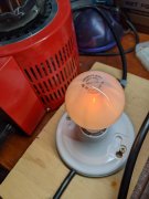
Well the most dreaded moment of the build arrived with installing the control board and slowly powering it up with the Variac and DBT. Three times I turned it back down and rechecked everything because I thought the bulb was getting too bright before the relay engaged.
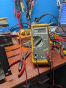
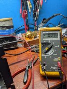
Success. .244 VDC bias on each channel with pots turned all way down, 000 VDC on each speaker jack. Bias adjusts up to .350 VDC and higher easily with equal clock position for each channel.

Good job George, your first 700....not a cherry anymore...
 
You've been careful all the way to now...no need to change..
 
If you build with the WOA backplane boards, which you did in this case, you can take all the nerves out of initial bring up by installing NO ouputs at all and bringing it up that way for initial checkout. It will give you the checks to ensure zero offset and bias circuits working (albeit low bias) before you put any devices in it. You will be able to see if your DCP relay clicks as well.
 
All outputs are in and she's running directly off line voltage with no Variac or DBT. Bias is set at .350 VDC both channels with same exact clock setting on the pots.
DC offset on right channel is .000 VDC, left channel is -.001 VDC.
I don't remember seeing a negative DC offset on the 400s or remember this being mentioned before. Is this a issue?
 

Attachments

  • PXL_20220101_170107810.jpg
    PXL_20220101_170107810.jpg
    3 MB · Views: 13
  • PXL_20220101_170124920.jpg
    PXL_20220101_170124920.jpg
    2.9 MB · Views: 13
No...offset is generally negative if there is any...
 
Offset is positive or negative on the RevE and G1 depending on the offset of the FET input of the OPA134. There is no typical direction for it. Rev D and earlier typically had negative offset voltage due to the NPN bipolar input stage it employed
 
Thanks Joe. Thinking about it, I do remember you explaining this on a old post.
 
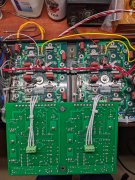
So look at all that room. Going to get some longer standoffs and space that control board away from the back planes a little more like Glen does his.
Going to lay a towel over the transformer and fins, lay the intermediate plate on it, and start wiring it.
 

Attachments

  • PXL_20220101_175419615.jpg
    PXL_20220101_175419615.jpg
    2.7 MB · Views: 41
Last edited:
I want to secure the power switch wires with nylon P-clamps on the intermediate plate, but the wire is about 3inches too short. Tearing it back down to install longer wire. I seldom get this right the first time.
 
Hi George
...The transformer bell can be connected to the transformer laminations. No problem with that. The through bolts must be isolated from the transformer core and end bell since the lines of flux cut through the bolts in normal operation and produce eddy currents in the bolts. The bolts also have to be isolated from the chassis. The transformer laminations and cradle can likewise be connected together and to the chassis. Just the bolts have to be isolated.

I just finished up a 400 with all of the goodies. Getting the transformer isolated was a challenge. I first tried heat shrink, which, to no surprise was too thick. I considered #12 screws and metric alternatives. While staring at the wall it hit me. Packing tape! The standard packing tape is a 1 7/8" wide. Here's the procedure.

1. Take a piece of packing tape about 8" long and lay it down on a bench, adhesive side up. Make sure the cut end is square.

2. Lay the bolt down parallel to the tape with the head against the edge of the tape.

3. Carefully roll it up like a joint. No wrinkles.

4. About 3/16" from the end use a knife to go around the bolt to cut the tape.

5. Grab the waste tape and pull it off the bolt.

The image below with the blue Sharpie ink was done to show the end of the tape on the threads. You can not see the end of the tape next to the head, but it does go right up to the head.

This technique provides about 3 layers of tape around the bolt. Before inserting the bolt in the transformer I pushed a 1/4" wooden dowel rod through the core to clean out any debris. If the tape is rolled up right it will go through with little resistance. Patience is a necessity. I had at least 10 failed attempts before all 4 bolts were wrapped. I used M8 nylon washers for isolation on each end of the bolt. I used flange nuts as seen in the last image.

Resistance readings from the bolts to the chassis and core were infinite. I would liked to have done a hipot test of 500 volts or so but lacked a safe way to do it.
IMG_3814.JPGIMG_3815.JPGIMG_3816.JPGIMG_3817.JPGIMG_3818.JPGIMG_3819.JPGIMG_3820[1].JPG
 
I just finished up a 400 with all of the goodies. Getting the transformer isolated was a challenge. I first tried heat shrink, which, to no surprise was too thick. I considered #12 screws and metric alternatives. While staring at the wall it hit me. Packing tape! The standard packing tape is a 1 7/8" wide. Here's the procedure.

1. Take a piece of packing tape about 8" long and lay it down on a bench, adhesive side up. Make sure the cut end is square.

2. Lay the bolt down parallel to the tape with the head against the edge of the tape.

3. Carefully roll it up like a joint. No wrinkles.

4. About 3/16" from the end use a knife to go around the bolt to cut the tape.

5. Grab the waste tape and pull it off the bolt.

The image below with the blue Sharpie ink was done to show the end of the tape on the threads. You can not see the end of the tape next to the head, but it does go right up to the head.

This technique provides about 3 layers of tape around the bolt. Before inserting the bolt in the transformer I pushed a 1/4" wooden dowel rod through the core to clean out any debris. If the tape is rolled up right it will go through with little resistance. Patience is a necessity. I had at least 10 failed attempts before all 4 bolts were wrapped. I used M8 nylon washers for isolation on each end of the bolt. I used flange nuts as seen in the last image.

Resistance readings from the bolts to the chassis and core were infinite. I would liked to have done a hipot test of 500 volts or so but lacked a safe way to do it.
View attachment 59649View attachment 59651View attachment 59653View attachment 59654View attachment 59655View attachment 59656View attachment 59658
Good idea Don. The 700s are easy because a McDonalds straw fits them nicely, the 400s, not so easy with the smaller diameter bolt.

That ultra thin plastic heat shrink that they use for battery packs would likely work OK too. Have not tried that or tried to locate it but there are many sellers of that stuff out there.
 
I just finished up a 400 with all of the goodies. Getting the transformer isolated was a challenge. I first tried heat shrink, which, to no surprise was too thick. I considered #12 screws and metric alternatives. While staring at the wall it hit me. Packing tape! The standard packing tape is a 1 7/8" wide. Here's the procedure.

1. Take a piece of packing tape about 8" long and lay it down on a bench, adhesive side up. Make sure the cut end is square.

2. Lay the bolt down parallel to the tape with the head against the edge of the tape.

3. Carefully roll it up like a joint. No wrinkles.

4. About 3/16" from the end use a knife to go around the bolt to cut the tape.

5. Grab the waste tape and pull it off the bolt.

The image below with the blue Sharpie ink was done to show the end of the tape on the threads. You can not see the end of the tape next to the head, but it does go right up to the head.

This technique provides about 3 layers of tape around the bolt. Before inserting the bolt in the transformer I pushed a 1/4" wooden dowel rod through the core to clean out any debris. If the tape is rolled up right it will go through with little resistance. Patience is a necessity. I had at least 10 failed attempts before all 4 bolts were wrapped. I used M8 nylon washers for isolation on each end of the bolt. I used flange nuts as seen in the last image.

Resistance readings from the bolts to the chassis and core were infinite. I would liked to have done a hipot test of 500 volts or so but lacked a safe way to do it.
View attachment 59649View attachment 59651View attachment 59653View attachment 59654View attachment 59655View attachment 59656View attachment 59658
Great idea Don! My 400 S2 was TIGHT, the S1 less so.
 
I just finished up a 400 with all of the goodies. Getting the transformer isolated was a challenge. I first tried heat shrink, which, to no surprise was too thick. I considered #12 screws and metric alternatives. While staring at the wall it hit me. Packing tape! The standard packing tape is a 1 7/8" wide. Here's the procedure.

1. Take a piece of packing tape about 8" long and lay it down on a bench, adhesive side up. Make sure the cut end is square.

2. Lay the bolt down parallel to the tape with the head against the edge of the tape.

3. Carefully roll it up like a joint. No wrinkles.

4. About 3/16" from the end use a knife to go around the bolt to cut the tape.

5. Grab the waste tape and pull it off the bolt.

The image below with the blue Sharpie ink was done to show the end of the tape on the threads. You can not see the end of the tape next to the head, but it does go right up to the head.

This technique provides about 3 layers of tape around the bolt. Before inserting the bolt in the transformer I pushed a 1/4" wooden dowel rod through the core to clean out any debris. If the tape is rolled up right it will go through with little resistance. Patience is a necessity. I had at least 10 failed attempts before all 4 bolts were wrapped. I used M8 nylon washers for isolation on each end of the bolt. I used flange nuts as seen in the last image.

Resistance readings from the bolts to the chassis and core were infinite. I would liked to have done a hipot test of 500 volts or so but lacked a safe way to do it.
View attachment 59649View attachment 59651View attachment 59653View attachment 59654View attachment 59655View attachment 59656View attachment 59658
Don, your idea is going to help a lot of people.
 
Making progress. The power switch was factory wired to use both sets of contacts with two buss wire jumpers on the bottom of the switch.
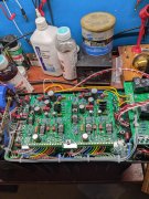
Decided to dress the full length of all control board wiring since I have plenty of that 1 MM sheathing. I do miss seeing the cool rainbow colors. Time to break and get away from this for awhile.
 

Attachments

  • PXL_20220101_220455108.jpg
    PXL_20220101_220455108.jpg
    2.8 MB · Views: 28
Back
Top