PL 700 Pro Build

Will check that out. Also several listings on eBay, some with silicone over the fiberglass. Now that you all helped me I'll do some research. Pretty sure I don't need silicone. Just simple fiberglass fabric tubing

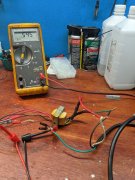
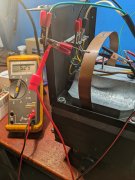
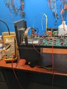
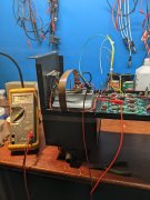
I use this brand silicone fiberglass tubing, you can see it in some of the pictures I have posted. neatens things up and provides great insulation.

Fiberglass Electrical Sleeving - Fiberglass Wire Sleeving Insulation | Electro Insulation Corporation
 
The silicone just keeps things together and lasts longer with monkeys.

When a plasma gun shorts, it’s pretty spectacular (and expensive)

75A4F2AD-895C-48F0-846A-5A8B512745E2.jpeg
 
Question: With the dual primary transformer in the PL2000 preamp, I found lowest noise on the unit using the PC based spectrum analyzer with Line connected to the striped transformer wires and Neutral connected to the solid color wires. Has anyone looked at this on the 700 dual primary transformer. I know I wired my 400 S2 like this when I installed the IEC socket.
 
Last edited:
So, that terminal strip mounted on the end wall is very handy to have. Makes wiring the dual primary transformer easy. If I ever go back into my 400s they'll be getting one of those.[/QUOTE]
I have added the terminal strip to the 400’s. Relocate it more towards top than center
 

Attachments

  • 8C5321D6-A1DC-4764-8252-50CC082F2748.jpeg
    8C5321D6-A1DC-4764-8252-50CC082F2748.jpeg
    906.7 KB · Views: 49
Question: With the dual primary transformer in the PL2000 preamp, I found lowest noise on the unit using the PC based spectrum analyzer with Line connected to the striped transformer wires and Neutral connected to the solid color wires. Has anyone looked at this on the 700 dual primary transformer. I know I wired my 400 S2 like this when I installed the IEC socket.

I have done a bunch of work in this area George. Much depends on the consistency of the winding formula that the transformer manufacturer uses. I am quite sure that PL left those details to the transformer manufacturer and did not provide them a winding sheet which would have made it a specification.

What I have found is that, generally speaking (and this all is conditioned by generally speaking because there are always exceptions):

  1. Transformer makers wind the primary first, closest to the core. Then layer secondaries on the outer winding layers, on top of the primary windings.
  2. With dual primaries, they will lay down a pair of wires at the same time to keep the primary wire lengths the same. Sometimes they use bifilar wire to do this, but not always.
  3. The end of both winding that starts at the core is where your hot wire should go to because these windings are farthest away from the secondaries that get layered on top of the primary windings. This will produce the lowest secondary coupling noise in a North American single phase application where the neutral wire in our homes is effectively earth ground.
  4. In European and other international high voltage applications. it matters much less because both primary input wires are hot. You don't get the US advantage.
  5. The noise is lower if you do this because you effectively have the ground end of the windings in close proximity to the secondary windings and therefore you get less capacitive and stray flux coupling noise between primary and secondary. That old trick of flipping the AC plug (before polarized plugs emerged on the scene) actually had some science behind it.
  6. I have done custom transformer work and provided a winding sheet to the manufacturer of the custom in order to control the winding sequence. Then I confirmed with measurements that the benefit of following the above guidelines actually does occur.
Hopefully this is helpful, and now it is documented here...
 
So, that terminal strip mounted on the end wall is very handy to have. Makes wiring the dual primary transformer easy. If I ever go back into my 400s they'll be getting one of those.
I have added the terminal strip to the 400’s. Relocate it more towards top than center[/QUOTE]

This is next leveling it...
IMG_2044.JPG
 
Joe, so how does one determine which end of the primary is closest to the core. I'm thinking it's the striped wires, but how to verify?
That's your new WOAD 400 chassis eh?
 
Hi George
Since the transformers you are using are built to some spec you don't know about, measurement is the only way to determine unless there are physical clues in where the wires exit the winding stack.

  1. Put your DMM on the VAC scale
  2. DMM lead 1 to secondary center tap, other secondary wires left floating
  3. DMM lead 2 to safety ground of your mains plug
  4. Shunt across your DMM with 100K ohm resistor to provide a light load to the transformer coupling effect
  5. Connect L and N to the primaries in one direction. Take measurement
  6. Flip the L and N to the primaries to get the other direction. Take measurement
  7. The lowest measurement is the orientation that you want to use.
Make sense?

No that is the White Oak Audio PL700 chassis pictured.
You lost me with L and N. Are those leads to a capacitance meter?
 
I have added the terminal strip to the 400’s. Relocate it more towards top than center

This is next leveling it...
View attachment 58556[/QUOTE]
I guess spade terminals are your preferred connection to the BR eh? I had wondered about that and went with soldered connections last two rectifiers I installed. I would assume you would recommend changing that procedure for
My next build?
 
Up to you Andrew but make sure you have good crimping tools (AMP/Tyco). Not those cheapy crimpers that really don't do a good job. Stick to the soldering if your transformer leads are the magnet wire coming out of the transformer.

The next leveling it is the barrier terminal block shown mounted to the far chassis wall.
 
Hi George
Since the transformers you are using are built to some spec you don't know about, measurement is the only way to determine unless there are physical clues in where the wires exit the winding stack.

  1. Put your DMM on the VAC scale
  2. DMM lead 1 to secondary center tap, other secondary wires left floating
  3. DMM lead 2 to safety ground of your mains plug
  4. Shunt across your DMM with 100K ohm resistor to provide a light load to the transformer coupling effect
  5. Connect L and N to the primaries in one direction. Take measurement
  6. Flip the L and N to the primaries to get the other direction. Take measurement
  7. The lowest measurement is the orientation that you want to use.
Make sense?

No that is the White Oak Audio PL700 chassis pictured.
Hi Joe, your technique works excellent! Just tested a PL2000 S2 dual primary transformer. This is the exact transformer I found had lowest noise with Line connected directly to the striped primary wires. Now going to test the 700 dual primary transformer.
 

Attachments

  • PXL_20211219_160040178.jpg
    PXL_20211219_160040178.jpg
    3 MB · Views: 22
  • PXL_20211219_160155415.jpg
    PXL_20211219_160155415.jpg
    2.9 MB · Views: 22
Last edited:
On this 700 dual primary transformer, line gets connected to the solid color primary wires. Hmmm, typical of PL, lax standards. Bummer, was hoping they had this standardized. Thanks Joe!!!
 

Attachments

  • PXL_20211219_163745203.jpg
    PXL_20211219_163745203.jpg
    2.3 MB · Views: 33
  • PXL_20211219_163646964.jpg
    PXL_20211219_163646964.jpg
    2.3 MB · Views: 33
Got the power supply wiring done. All 14 AWG silver plated PTFE insulated. First time putting power to the transformer since I received it. +102 VDC and -102 VDC. Weren't some of the 700 Series 1transformers wound hotter than this? Seems like I remember the 400s being + and - 80 VDC.
 

Attachments

  • PXL_20211219_220408951.jpg
    PXL_20211219_220408951.jpg
    2.3 MB · Views: 17
  • PXL_20211219_220430251.jpg
    PXL_20211219_220430251.jpg
    2.5 MB · Views: 17
It was completely random George, but it seems a majority of the hotties were made by Bob's stoner brother when he was the transformer winder...in the Ser I's...

Some Ser II's like Darcy's were 108...
 
Back
Top